By Kristen Cart
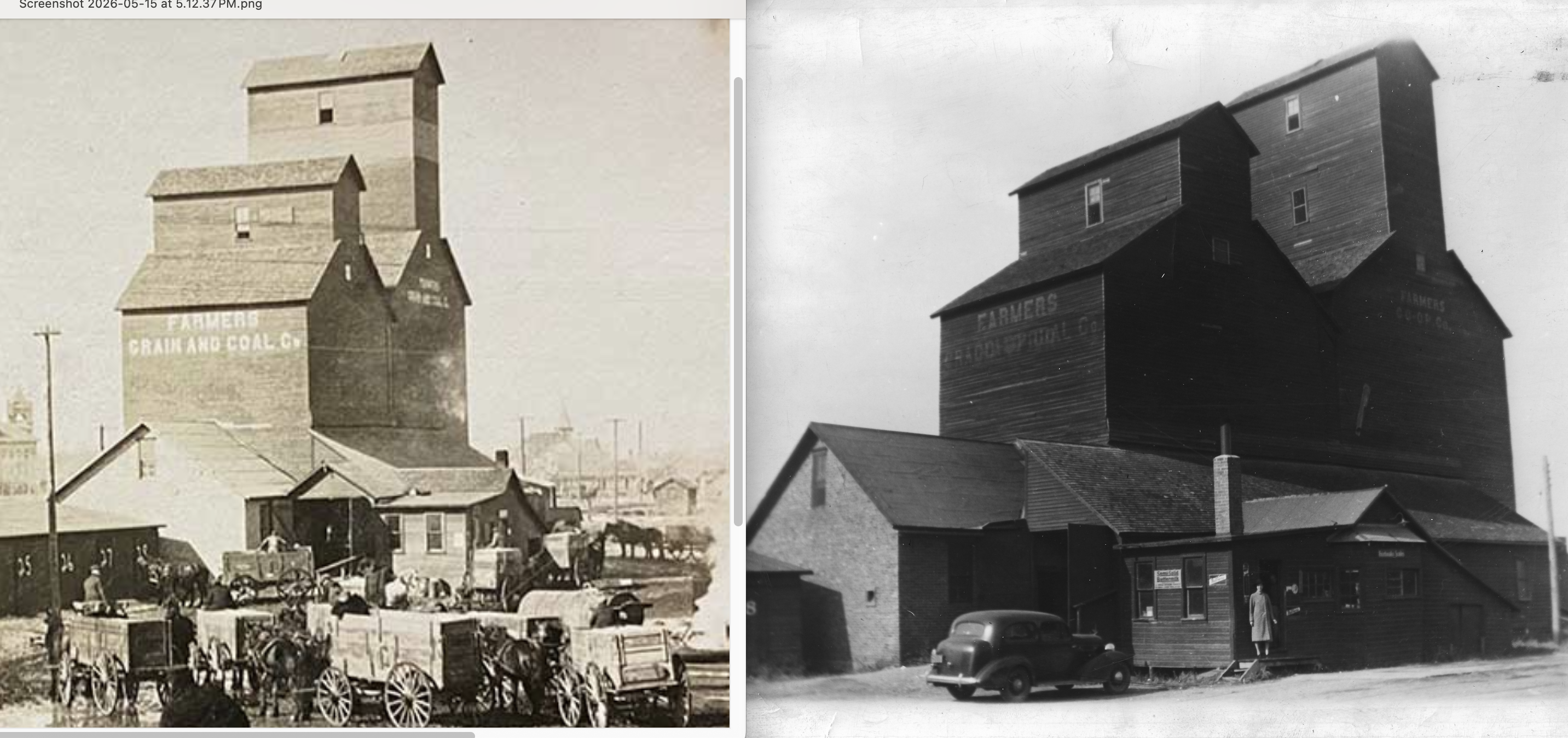
My blogging partner Ronald Ahrens posed a question for our readers. Where in the world was this old elevator shown above on the right? Like most wooden elevators from the early days, it was likely demolished years ago. After a productive internet dive, one of our loyal readers, Suzassippi, found the answer. I combined the elevator picture she found with our mystery image to compare the two.
The earlier photo was clipped from an image posted in Suzassippi’s comment. It shows horse-drawn wagons and an ancient elevator. The caption identifies the site as Pocahontas, Iowa, from the early 1900s. The two images above were photographed from slightly different vantage points, but they look uncannily alike.
You can see that a few details had been altered by the time the later photo was taken. For one thing, the 1930s-vintage car was a giveaway. Plainly, many years had intervened since the earlier image. You can see that a chimney relocated from one side of the scale-house to the other, a bay window was added, and an intriguing alteration to the roof line occurred just in front and to the left of the vehicle. I puzzled and puzzled over that oddity–the roof had been changed, but I couldn’t figure out how it fit with the existing roof line. Perhaps the perspective made it appear to attach at an impossible angle. Maybe it’s just me.
The doors to the driveway appeared unchanged, swinging outward rather than rolling up. The structure directly in front of the car was the scale-house, adjacent to the covered driveway, where the telltale roof line and window locations appeared to be just so, except for where the roof was extended. Finally, the painted lettering on the elevator closes the deal. Much faded, it was still precisely where it appeared in the earlier photo, years before. Undoubtedly, our mystery elevator was located in Pocahontas, Iowa.
That leaves us with the question of why the elevator photo was found with the Tillotson archive. If the family was involved with the building, renovation, or demolition of this particular elevator and its associated buildings, we have no proof of it. However, this item from the Pocahontas Record Democrat of Oct. 3, 1940, may give a clue:
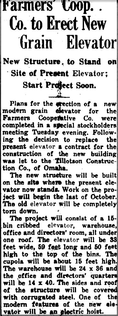
We know Van Ness Construction Company was headquartered in Fairbury, Nebr. before 1917, perhaps early enough to have built this old elevator. But they were involved with many other aspects of elevator construction and destruction, so we don’t know, and nothing yet explains the later photo. Was this the old elevator that Tillotson Construction Company replaced in 1940?
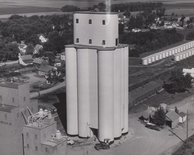
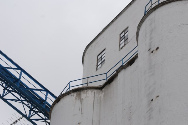
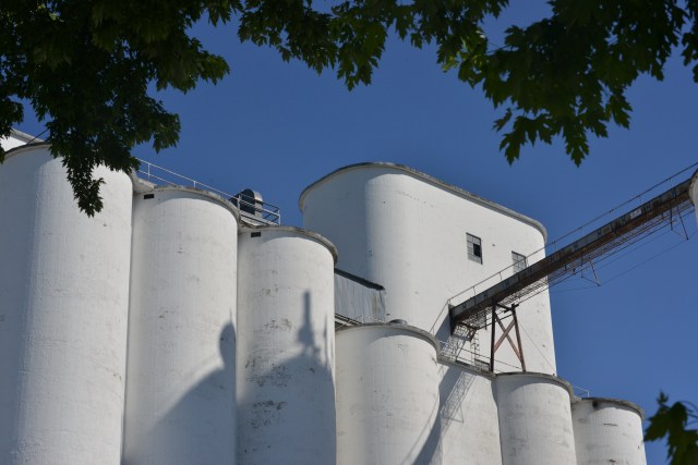
Tillotson Construction Company of Omaha built a new elevator of reinforced concrete in Pocahontas in 1954, when it splashed across newspapers in all of its slip-formed concrete glory. Charles J. Tillotson “walked the plank” during the construction. Evidently, the Tillotsons had a long standing connection with the location, but we have not teased out where this old wooden edifice fits into the timeline.