The men and women of slip-formed concrete and the buildings they created in North America
Category Archives: Drawings
A collection of scanned blueprint and blue line drawings from Tillotson Construction Co. archives, showing details of reinforced-concrete grain elevators of various sizes.
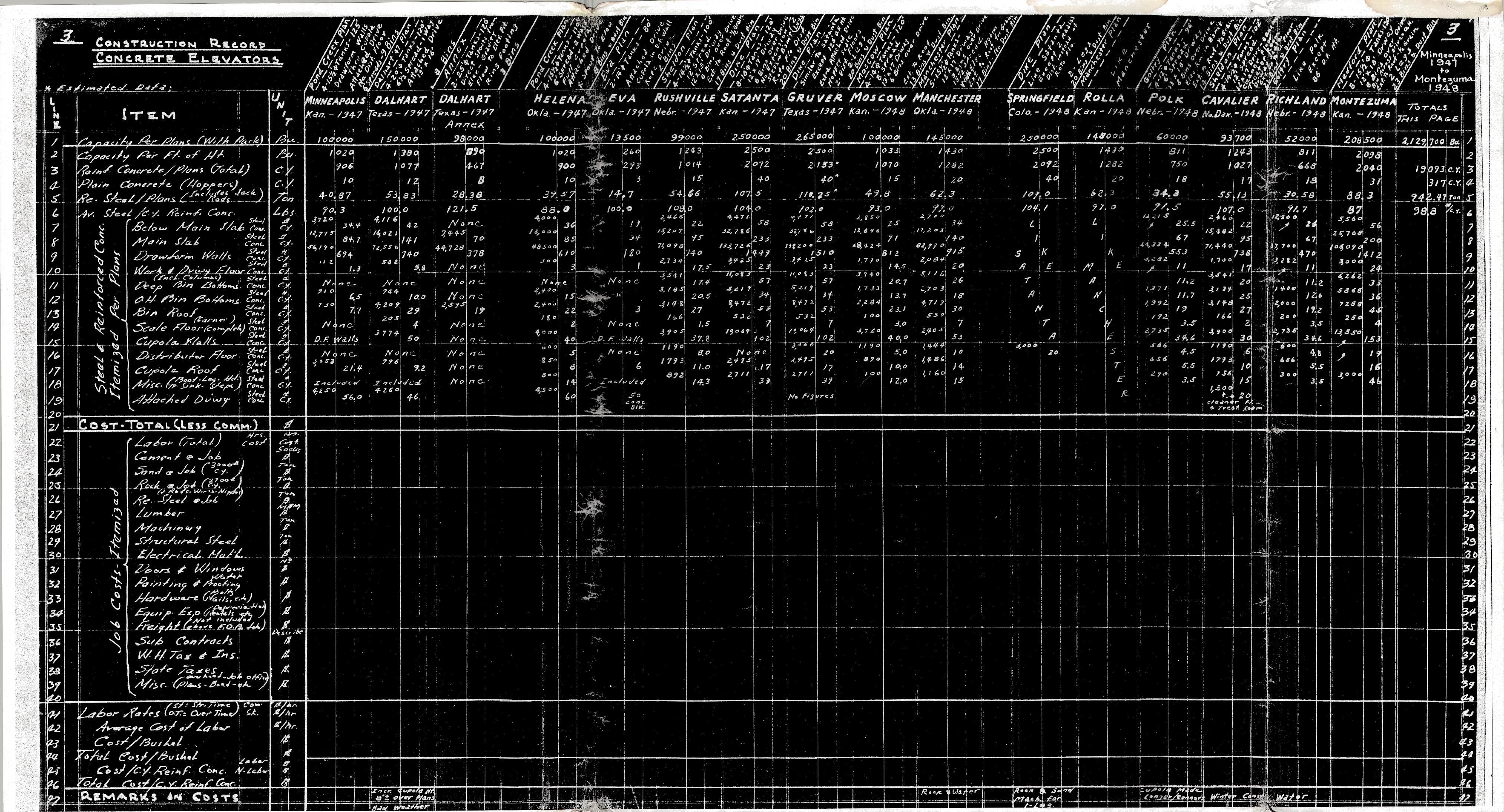
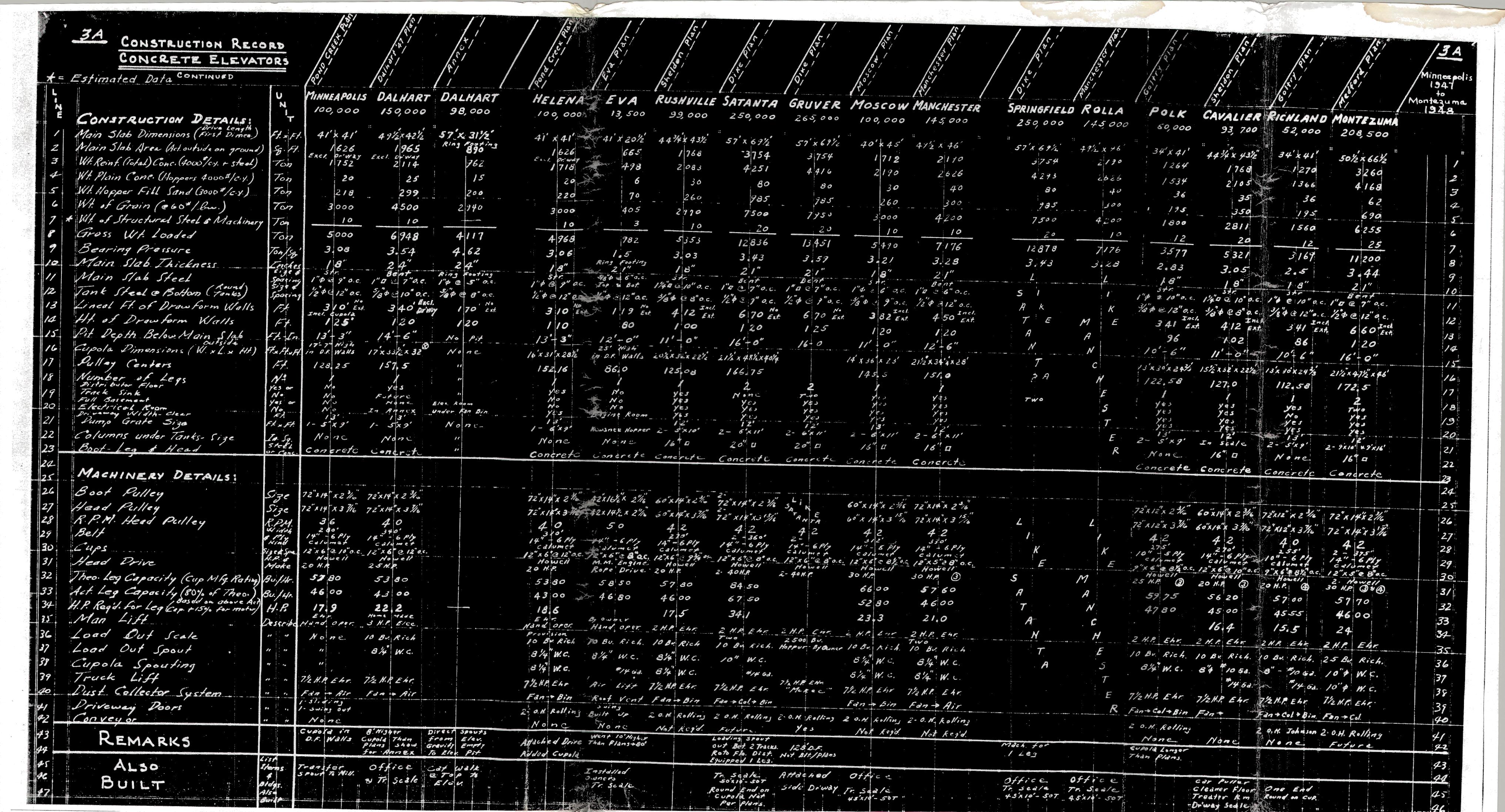
Pages 3 and 3A of the Tillotson Construction Company’s construction record duplicate pages 2 and 2A from a previous post, but these are the complete scans of full long pages. The extra information concerns Cavalier, N.D.; Richland, Nebr.; and Montezuma, Kan.
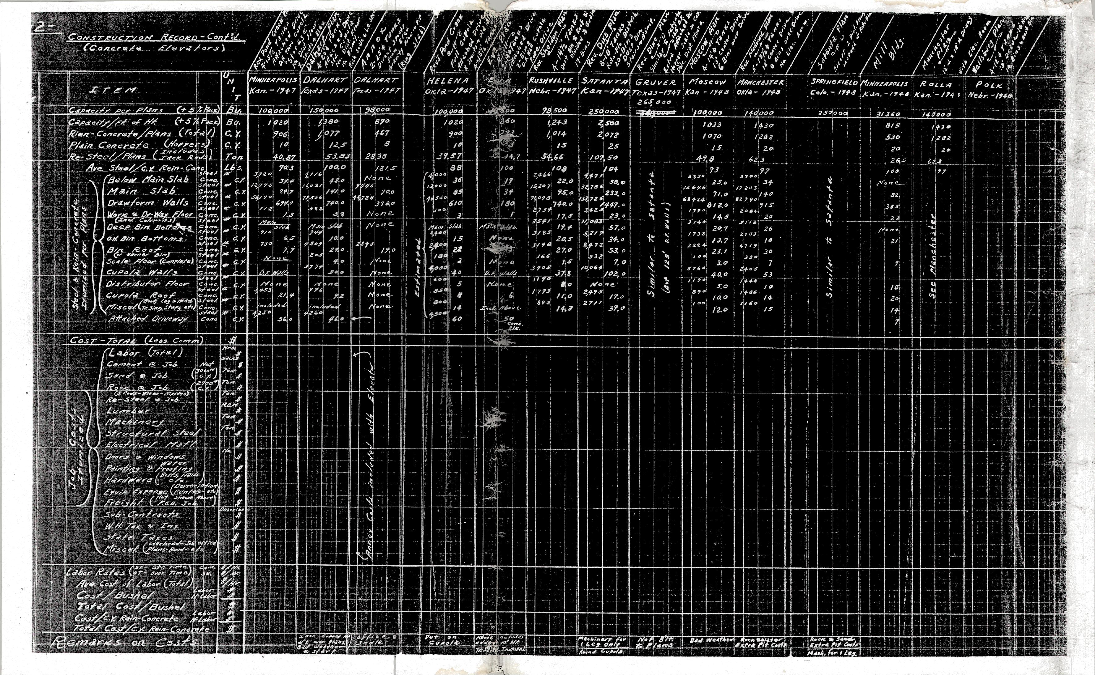
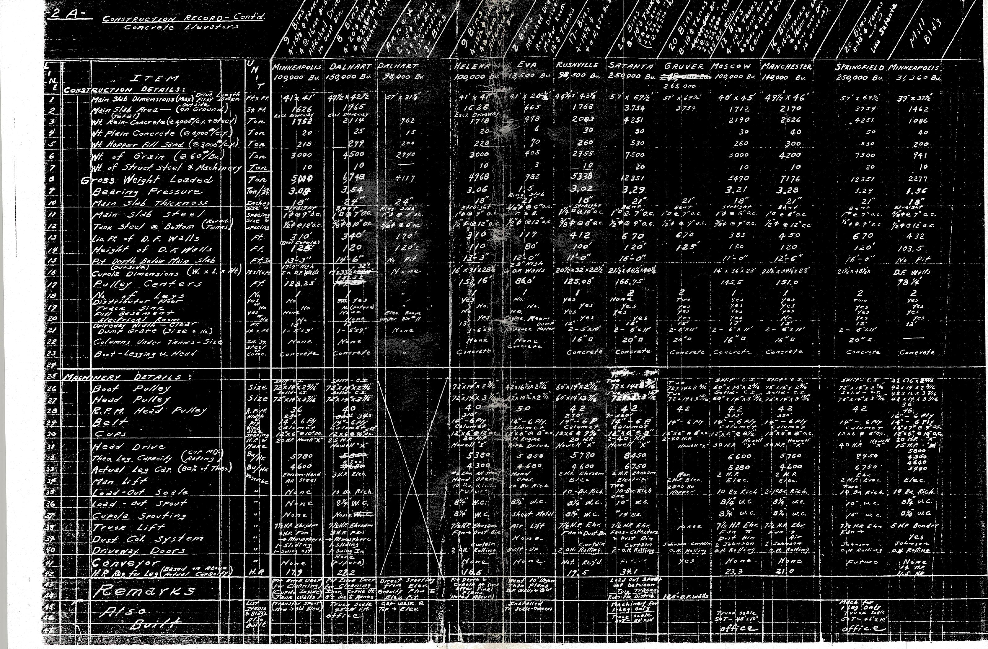
Pages 2 and 2A of the Tillotson Construction Co. record of concrete elevators cover jobs in 1947 and 1948. The pages start at Minneapolis, Kan. and extend to Polk, Nebr. The jobs range in size from a 31,360-bushel mill building at Minneapolis, Kan. (in addition to the 100,000-bushel elevator) in 1948 to a whopping 265,000-bushel elevator with 125-foot drawform walls in Dalhart, Tex.
Page 1, which started the record in 1939, included cost information, but those figures aren’t included here.
Locations represented in these records are Minneapolis, Kan.; Dalhart, Tex.; Helena, Okla.; Eva, Okla.; Rushville, Nebr.; Satanta, Kan.; Gruver, Tex.; Moscow, Kan.; Manchester, Okla.; Springfield, Colo.; Rolla, Kan.; and Polk, Nebr.
Be sure to look at the bottom of p. 2 for notes on adverse weather and other challenges that factored into these jobs.
Here at last we present a digitized page of the Tillotson Construction Co. record the late Tim Tillotson duplicated in 2012. Kristen Cart took the whole load of dupes to a copy center, and her effort leads to a batch of pages to be shared over the next few weeks. In that service, we’ve created a new subcategory of the blog for the records’ easy location.
Tillotson Construction Co. was formed in Omaha by Reginald and Joe Tillotson in 1938. Their first concrete elevator, listed on this page, was a 60,000-bushel job in Goltry, Okla. We visited that location in 2018.
Rose A. Tillotson was widow of Charles H. Tillotson and mother to Joe and Reginald.
The reader will note the company got off to a fast start until 1941 when World War Two intervened. There is a three-year gap until the next job in 1944. The page lists more from then until 1946. The jobs got much bigger–up to 350,000 bushels at Farnsworth, Tex. (Good luck squeezing “Farnsworth” into a narrow column heading!
We visited some of these locations on our 2018 Texas-Oklahoma road trip.
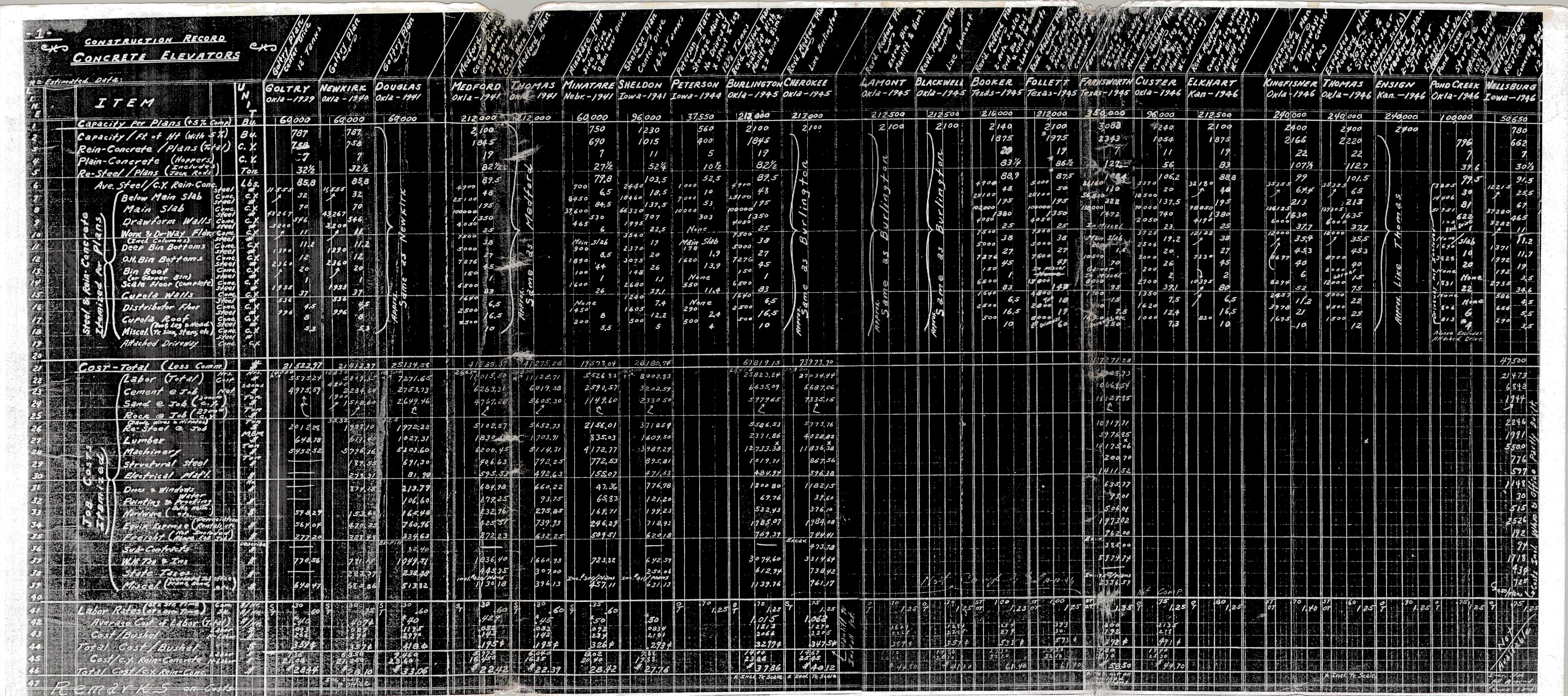
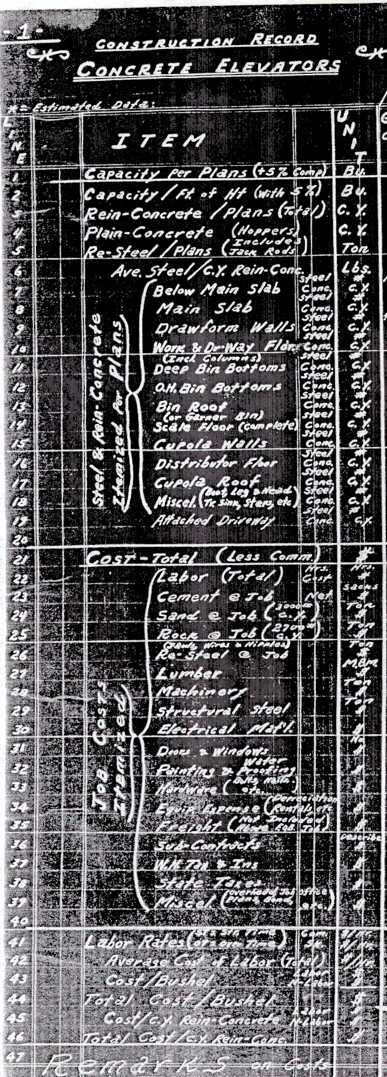
Job sites are written atop the page with the year of construction. Most note which plan the elevator follows and extra information such as location of the driveway or diameters of the tanks. Zooming in splendidly reveals meticulously written entries. Uncle Tim told us the name of the employee who started this record. Maybe it’s in one of our early posts.
A key to reading this table: The left-hand column headed by “Item” lists various specifications such as gross capacity of the elevator and amount of rebar used per cubic yard of concrete in varying locations throughout the structure.
The middle section is devoted to costs (less commission) for labor and materials and even includes a line for state taxes. Only a few of Tillotson’s subsequent records include costs.
The bottom block has more info about total dollars and labor rates. At the very bottom, the notes are ad-libbed. They elaborate mundane points. One, for example, indicates total cost included a scale and office.
All in all, it’s a direct connection to answers on a great many points of Tillotson elevators.
We are pleased to introduce you this week to Rev. David Herbert Hatch. He leads a Lutheran congregation in Green Bay, Wisc. but cut his teeth in elevator construction during the 1970s when hydraulic jacking had replaced the mechanical means.
David Herbert Hatch is senior pastor at Our Savior Lutheran Church in Green Bay, Wisc. He worked slip-form construction on elevators throughout Iowa in the early to mid 1970s.
In this post and the coming series, Dave supplements his recollections with original drawings. These are especially noteworthy because of his colorblindness.
He writes: If I could leave this for your imagination …
An extremely heavy concrete bucket free-falling to the ground at an unknown speed for about 150 feet until the brake man on the winch brings it to a timed stop in front of a concrete truck driver on the ground below.
What if my foot had slipped off the brake?
Likewise, imagine an entirely full concrete bucket, running up the side of a grain elevator at full throttle and I got distracted just before it came to the pulley on the gin pole at the top … what would happen to the guy in the hopper or those below?
This was so intense for me, I would sit up in the middle of the night, operating the winch in my sleep.
I wonder why there’s a ringing in my ears. Hours and hours of running an industrial engine, a few feet away from me, at super-high RPM.
My brother-in-law worked steel. There was a bunch of us, my friends, who would camp–or crash in motels around the state–and go from slip to slip.
The experience gave me a hunger to be a crane operator, which never happened.
About getting concrete to the deck during active slip-form pouring:
Looking at the photographs of current construction, I can see concrete pumps and tower cranes. My company, Todd & Sargent, tried a concrete pump once and it plugged up! Yikes!
During my days, we used a winch that was anchored into the earth. That was our normal way of getting the mud to the top, one slip operation after another.
The winch was perhaps 200 to 300 feet away in the base of the tanks.
There were three pulleys involved. One at the base of the tank near where the concrete truck was and two up on the gin pole on the deck.
The Concrete Hopper
Above the deck was the concrete hopper.
Vertically next to the hopper was the gin pole. It had a handle so the bucket-dumper guy could swing the bucket in and out.
This hopper was directly above the concrete trucks below.
A guy stood on a platform next to the hopper. As soon as the bucket came up and stopped, and as fast as he could, he pulled the bucket in and dumped it into the hopper.
A light concrete splash went flying everywhere, everytime. Safety glasses for sure. That concrete spit often dropped down into your gloves, burning your skin.
And then, fast as he could, he threw and/or pushed the bucket out into open air to begin its freefall to earth for refilling. The winch operator controlled that.
Being hopper-guy was fun for many reasons: timing, repetitive actions, striving for efficiency and grace. Could it be graceful to pull in a bucket, dump it, and throw it to the wind as fast as you could? Yes! And you were working with some invisible guy on the ground you never saw or met: the winch operator. You were a team. You never communicated. It was like you were playing catch, back and forth as fast as you could, with bucket of mud. I kinda miss it!
David Hatch was born and raised in Ames, Iowa. Prior to college studies, Pastor Dave worked construction, and had hopes of serving in law enforcement until his partial color-blindness prevented that. He did not know what to do with his life. Through God’s Providence and a phone call from his sister, who was a kindergarten teacher in Milwaukee, he enrolled in a college where, unknown to him, many of his future classmates were studying to be pastors. He received his education at Concordia College in Milwaukee; Concordia Teacher’s College, River Forest, Ill.; and Concordia Theological Seminary, Fort Wayne, Ind. His pastoral career began in 1982, following seminary, when he served as an admissions counselor at Concordia College in Bronxville, N.Y. and parish pastor at Love Lutheran Church outside of Albany, N.Y.
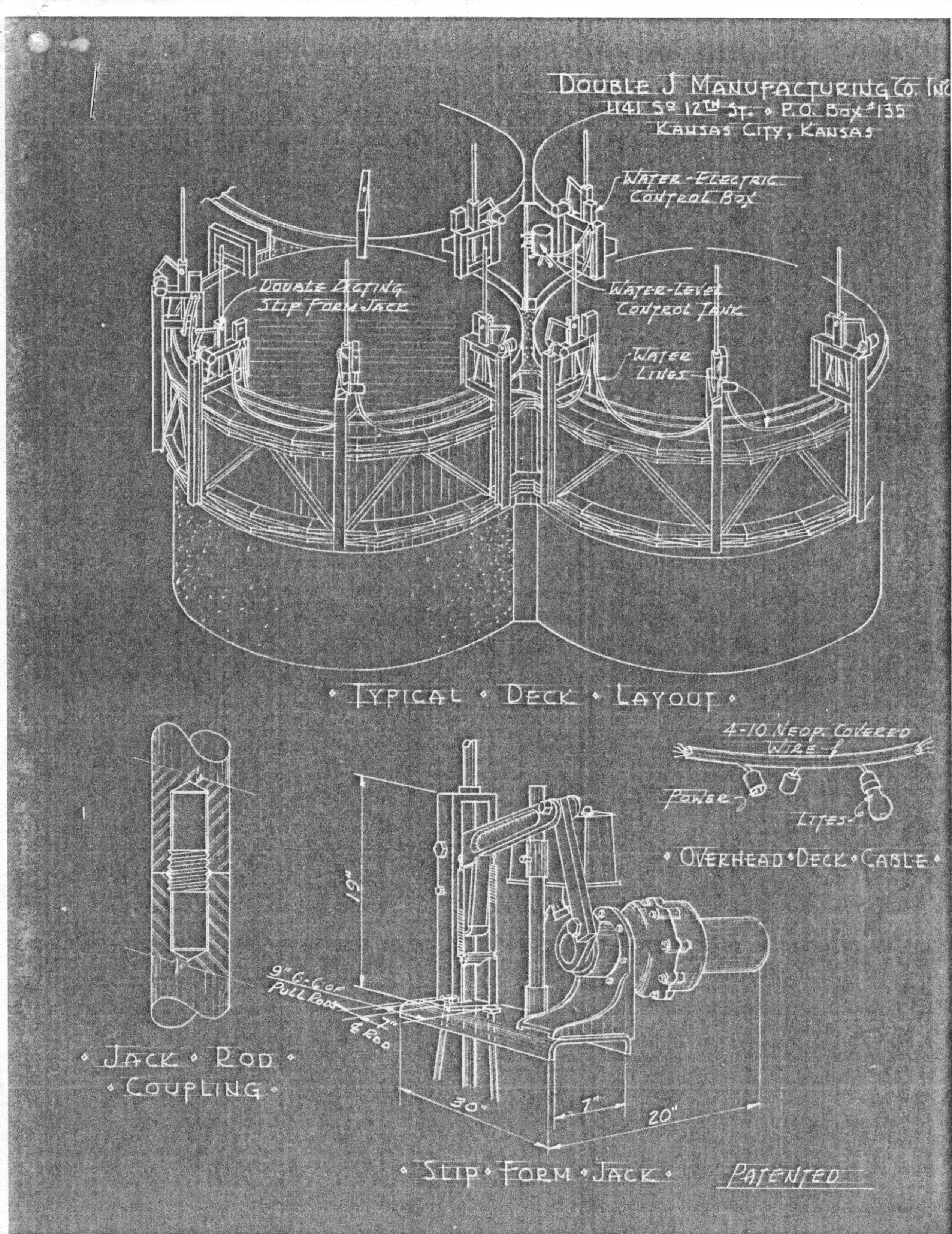
The viewer can take his or her own meaning from the drawing, but allow us to point out the inset illustration labeled “Overhead Deck Cable.” It shows 4-10 neoprene-covered wire with power outlets and “lites” rendered in such charming style. (Neoprene was invented by Dupont in 1930.)
Traces of Double J Manufacturing Co., Inc.–which opened in 1949–turn up in a web search. Double J is characterized as a producer of industrial and commercial machinery and equipment. There’s even a phone number, but dialing 913.342.4400 yields, “We’re sorry, you have reached a number that has been disconnected or is no longer in service.”
Nevertheless, this excellent drawing commemorates the company.
Finally, mercifully, we get to the last of the drawings from Tillotson Construction Co. records, and instead of dark, hard-to-read copies of blueprints, we offer these scanned copies of a “blue line.” They’re for a main slab and tunnel at Gurley, Neb.–which we assume has something to do with an annex–and were completed by Ted Morris on April 18, 1958. The scale is indicated as one-quarter-inch to one foot.
These are among the most detailed drawings in our possession, with abundant dimensional markings and figures for steel reinforcing bars. There are also many notations, some comprehensible and others begging for clarifying comments. In the upper right, the note, “Knock out Exist. Endwall in Tunnel” seems to suggest a conveyor that would connect the annex to the elevator.
Above that, an 11.0-foot gap is indicated between slabs with the note, “Wall to Wall (to Clr. Car Puller). Hmm!
Another one, between the Number Six and Number Four tanks, says, “Truss Bars next to Tank Opg’s. Str. Bars next to Inner Opgs.”
And in Number One we read, “Main Slab Steel to be 2″ Clear from Face of Slab Shown. Main Wall Steel to be 3/4″ clear from Face of Wall Shown.”
Others are far trickier. For example, “Print Walls for Roof” is written in Number Eight, and that’s pretty obscure.
Gurley is located in the Nebraska panhandle a few miles north of Sidney and Interstate 80. A satellite view reveals the annex and main elevator quite clearly amid Crossroad Coop’s complex at 501 Lincoln St. and ought to satisfy reader Suzassippi’s desire to match the two-dimensional drawing with a photographic view.
Readers may please feel free to contribute their own interpretations via the comments feature.
Among the most detailed drawings in our possession is this print, from the records of Tillotson Construction Co., of Omaha, for a 100,000- to 129,000-bushel, single-leg reinforced-concrete grain elevator.
We assume that Ted Morris executed the drawings for the company. We do not see notations for the scale of these drawings in inches to feet, as in others previously posted. Otherwise, the drawings are meticulously rendered.
To the left above is the cross-section of the structure. The main house has four tanks (silos) with internal diameter of 14 feet six inches and, with 100-foot drawform walls, a 102,500-bushel capacity is achieved. At 120 feet, the capacity increases to 128,900 bushels.
The cupola is marked as 22.0 feet high and 34.0 feet wide. Special markings indicate the dimensions of segments within and atop the cupola. A notation at the roof indicates the centerline of the driveway far below. We also see inscriptions for the head pulley, top of manlift travel, an interior ladder nearby, and to the far left, a 10-inch-diameter, 14-gauge spout.
In the main house, bins are numbered. From left to right, we see internal Bins 5, 11, 12, and 15.
Above the driveway and work floor, a space that extends 17.0 feet accommodates the 12.0-foot steel overhead-curtain-type door and electric truck-lift rails. The grate is 9.0-feet wide. The pit goes 12.0 feet below the main slab. A note indicates “Typ. Base Sash Elev.,” the meaning of which is open to interpretation although it obviously refers to a window. An entry in the Standard Machinery list includes, “Industrial steel windows & Doors @ Cupola & Work Floor.”
Below the cross-section is a Boot Pit Plan showing two pits and a ladder up, with dimensions given.
The Bin and Foundation plans give the various specifications and dimensions, including a 44.0 x 44.0 slab and 9 foot 9-inch radius from center of a tank to the outside perimeter.
The Bin Roof & Cupola Floor Plan includes such juicy details as the dimensions of wall openings under the roof and louvres under eaves and indicates three “B24141 cpd” windows. A key to symbols explains markings for “C.I. 24-inch manhole [with] ladder below,” “C.I. 20-inch roof scuttle,” “S.M. 20-inch removable grate and cover,” and 10-inch 14-gauge spouts. The scale is rated for 10 bushels.
The Work Floor and Driveway Floor Plan shows the driveway curtain door is 11.0 feet wide and opens to an area with 13.0 feet of clearance. The two dump grates are indicated. No. 1 is 9.0 x 3.5 feet )or it could be 5.5 feet), and No. 2 is 9 x 15 feet. Doors are 3070 doors.
The Distributor Floor Plan depicts 18 funnels at 16-inch centers, and a radius of 4 feet 7 inches from center. There are four of the B24141 C.P.O. windows.
The Scale Floor Plan shows the scale, a ladder up, and the load-out spout, as well as various dimensions.
The list of Standard Machinery includes the following:
Head & Boot Pulley 60 x 14-inch C.I.
Belt 14-inch, six-ply
Cups 12 x 6-inch Calumet at 9-inch centers
Leg capacity 5,000 bushels/hour
Head drive 25 or 30 H.P.
Truck Lift 7 1/2 H.P. Elec.
Manlift 2 H.P. Elec.
Dust col. System 3 H.P. Fan @ Head, Disch[arge] to Bin
Leading Out Scale 10 Bu. Richardson
Leading Out Spout 8 1/4-inch well casing
Cupola Spouting 10-inch-diameter, 14-gauge steel
Car Unloading Facilities By Gravity, Direct to Boot
These drawings reproduced from the records of Tillotson Construction Co., of Omaha, show the general-plan details of a 100,000- to 125,000-bushel, single- or twin-leg, reinforced-concrete elevator.
To the left above, seen at the scale of one-eighth inch to one foot, is the cross-section of the structure. The main house has four tanks (silos) with internal diameter of 14 feet six inches and, at 100 feet in height, a 100,000-bushel capacity is achieved. At 120 feet, the capacity would increase to 130,000 bushels.
The cupola is marked as 22.0 feet high with a single leg and 30 feet 6 inches with two legs. Notations inscribed in the cupola space label the dust fan, distributor floor, automated scale, and cupola floor. The diameter of the leg’s head pulley is 60 inches.
In the main house, bins are numbered. From left to right, we see Bin 5, Bin 11, Bin 12, and Bin 15.
Above the driveway and work floor, a space that extends 17.0 feet accommodates the steel overhead-curtain-type door and electric truck-lift rails. The main slab is indicated below.
At the very bottom, we see a 13 foot 6 inch depth for the pit with a single leg or 15 foot 9 inch depth for a twin-leg setup.
The driveway floor plan (center) is rendered at the scale of one-quarter inch to one foot. To the far left, we see a dock. The measure of 13.0 feet is given between the two tanks (Numbers 1 and 4). The driveway is 47.0 feet long–three feet longer than the main slab. It is 30.0 feet from the initial edge of the second dump grate to the driveway exit. The width is 13.0 feet. On the right are the electrical room, an electrically operated manlift, and a manhole.
The variation drawing, “Dvwy Floor Plan 2 Legs,” at the same quarter-inch scale, includes details for a twin-leg elevator. The note at bottom says, “Remainder of Plan same as with 1-leg.”
The Bin Plan at the right shows a 44.0-foot width. (So the main slab is apparently 44.0 x 44.0 feet.) At top we see a dust bin noted as well as bin draw-offs in the interior bins. A number of those bins are marked as 10 feet 4.5 inches across. Number 12 is 7 feet 11 inches wide. Number 16 is 12 feet 10 inches.
At lower right, the twin-leg variation drawing shows the distribution-control cable well–not indicated in other drawings we’ve posted–and the manlift and ladder well and manlift weight box.
The large tanks Numbers 1 to 4 are shown in counter-clockwise order from the upper right. At 100,000-bushels overall elevator capacity, Numbers 1 and 4 hold 11,996 bushels. Numbers 2 and 3 hold 12,066 bushels. At 125,000-bushel capacity, Numbers 1 and 4 hold 14,770 bushels. Numbers 2 and 3 hold 14,840 bushels.
The internal bins are at 100,000/125,000-bushel ratings as follows for single and twin-leg configurations:
Bins 5 & 6: 4,555/5,7770 bushels
Bins 7: 2,207/2,400 bushels
Bin 8, 13, 14: 4,217/5,400 bushels
Bin 9 & 11: 6,030/7,730 bushels
Bin 10: 4,790/6,140 bushels
Bin 12 (scale): 4,452-4,014 (1-2 leg)/5,800-5,460 (1-2 leg) bushels
Bin 15: 4,858 (1-2 leg)/6,150 (1-2 leg) bushels
Bin 16: 4,790-4,465 (1-2 leg)/6,070-5,655 (1-2 leg) bushels
These drawings reproduced from the records of Tillotson Construction Co., of Omaha, show the general-plan details of a 150,000-bushel, single-leg, reinforced-concrete elevator.
To the left above, seen at the scale of one-quarter inch to one foot, is the cross-section of the structure. The main house has five tanks (silos) with internal diameter of 16.0 feet and achieves a height of 120 feet. No dimensions are shown for the cupola; the only notation in the plan says “automatic scale.”
In the main house are notes saying, “Up Leg” and “Down Leg. Other say, “Elect. Truck Lift” and “Dump Grate.” The driveway door is 13.0 feet high.
A precisely rendered rail car provides a fanciful touch on the far right, where it’s positioned at the load-out spout to receive a cargo.
At the very bottom, we see a 21.0-foot depth below the main slab.
The work floor plan (center) is rendered at the scale of three-sixteenths inch to one foot. We see that the whole structure sits on the slab measuring 50.0 x 47.0 feet. Internal diameter of the tanks is 16.0 feet. Notes show the locations of the electrical room, two manholes, dump grates, and at far right the dock.
The bin plan, also three-sixteenths to one foot, shows the five large tanks with Number 1 in the lower-right and the progression going counter-clockwise to Number 5 on the lower-left.
Sandwiched inside are Bins 6 through 16. We see that Bins 6, 8, 10 and 12-16 are marked as being 10.0 feet wide. Bin 9 is 7 feet 6 inches across. Bin 14, on the far right, is 13 feet 9 inches across. Bin 16 is labeled “Dust Bin.”
The large tanks Numbers 1 to 5 have capacities of 17,650 bushels. The internal bins are as follows:
Bins 6-7: 5,300 bushels
Bins 8 & 10: 6,790 bushels
Bin 9: 6,000 bushels
Bin 11: 6,540 bushels
Bin 12: 2,640 bushels
Bin 13: 5,300 bushels
Bin 14: 8,220 bushels
Bin 15: 7,980 bushels
Bin 16 (Dust Bin): 930 bushels
Unlike any of the other plans we have, this one is dated. One entry in the lower-right says, “Rec’d 3-3-58.” There are two other illegible dates, but at very bottom another date shows 3/31/58.
The initials “TM” would seem to indicate that Tillotson’s Ted Morris executed the drawings.