The twin of the vanished Glidden, Iowa, elevator still stands at Churdan, Iowa

DSC_0476Story and photos by Kristen Cart

Tucked into a nest of grain bins in the west-central Iowa town of Churdan is an old original elevator built by Tillotson Construction Company of Omaha, Neb. The annex hard by its side also boasts the Tillotson name.

DSC_0454

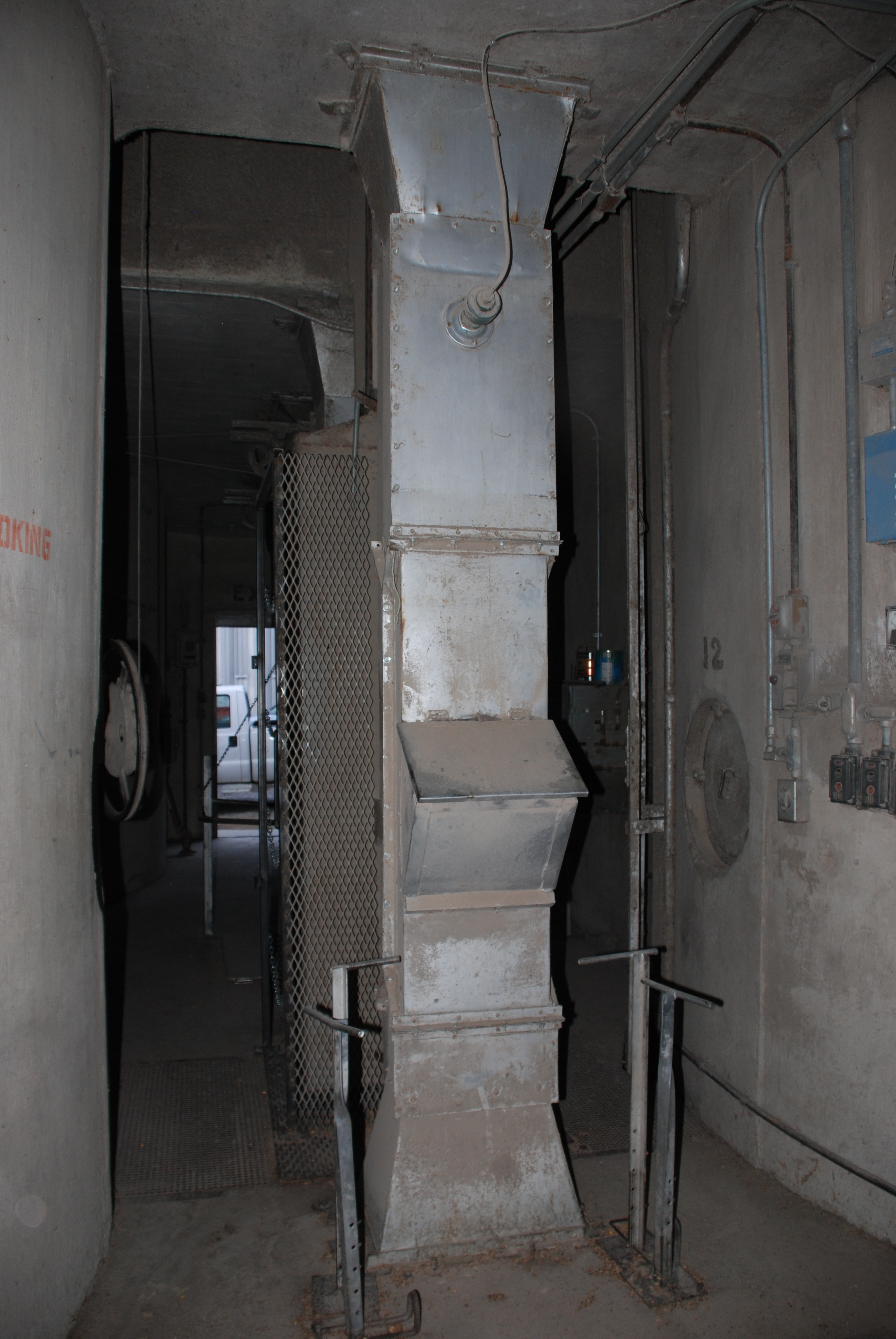
It is immediately obvious that the old Tillotson structure has been updated at some time in the past with a leg that extends above the headhouse, thereby keeping the machinery most prone to overheating far from accumulations of grain dust.

DSC_0497DSC_0490The annex beside it shows signs of cracking. Stress cracks are an old enemy of elevators, a problem which eventually spelled the demise of the Churdan elevator’s twin at Glidden, Iowa, and also the Mayer-Osborn elevator at Maywood, Kan.

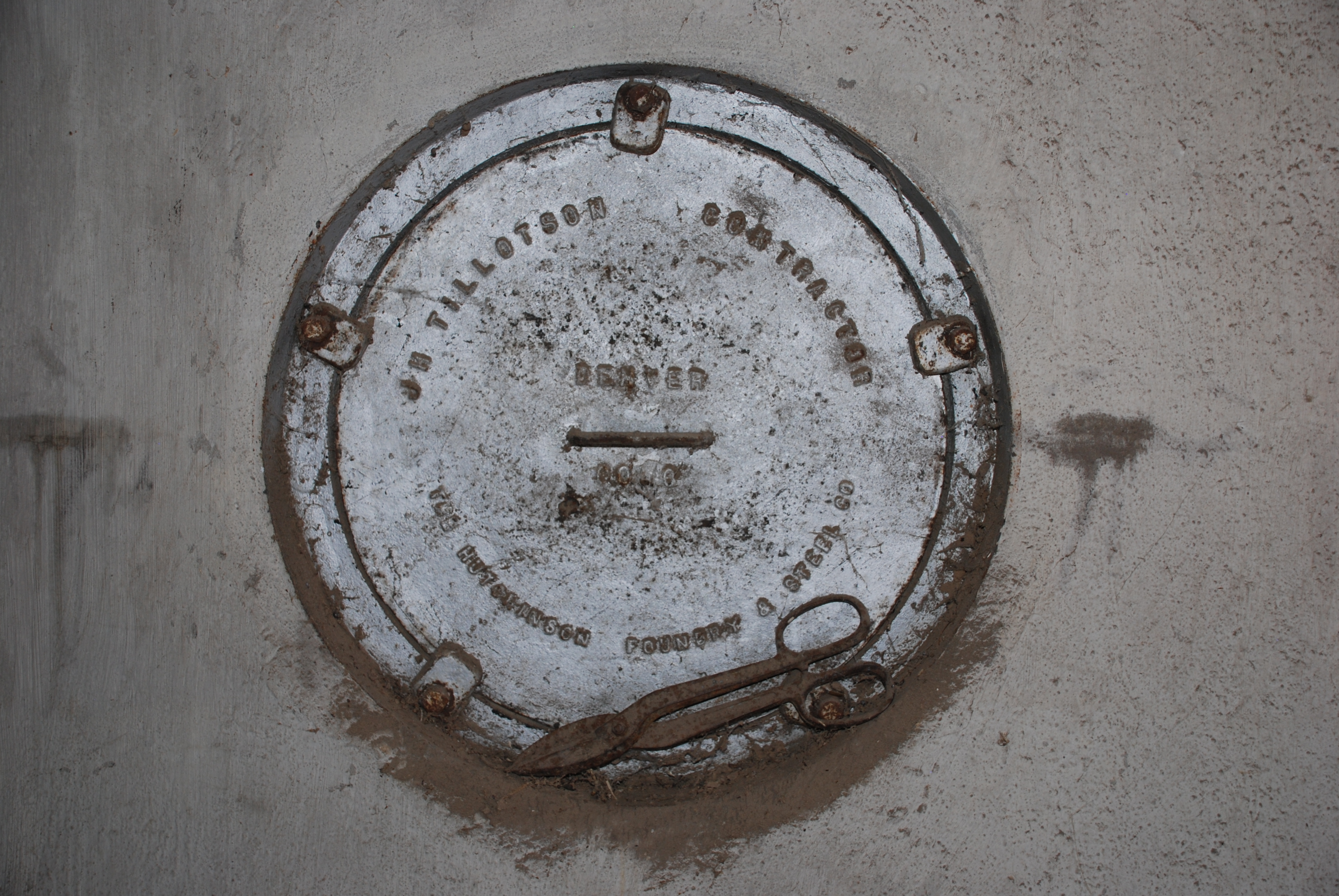
Manhole covers along the side declare that the annex was built by Tillotson Construction in 1955.

DSC_0486An elevator built by Quad States was added to the Farmers Cooperative complex some years later. (Its trademark stepped headhouse is curved only at the outside margins, a usually reliable indicator of a Quad States design. A manhole cover dated 1969 boasts its provenance.)

A white-painted metal bin, served by the Tillotson elevator headhouse, was also added to the site to increase storage capacity.

DSC_0463

Click the photo to witness the demolition

After demolition of two faulty bins in 2013, the concrete remnants were bulldozed into the center of an empty lot across from the co-op office.

A large-capacity shiny metal bin across the street completes the scene.

We are fortunate to have the specifications for the Churdan elevator, which is an early example built in 1949, and for its 198,960-bushel annex. The elevator specifications are detailed below.

The “Churdan Plan” was used for a number of Tillotson elevators, including Glidden, Sanborn, Gilmore City, and Thompson, Iowa; Greenwood and Fairfield, Neb.; and Montevideo, Minn. The construction of elevators using this plan spanned from 1949 to 1952. Specifications varied according to an individual customer’s  requirements.

The “Churdan Plan” consisted of four 14 1/2-foot-diameter bins, 100 feet tall, with a 13-by-17-foot driveway and eight bins over the driveway. It had a 13-foot spread. Notations in the company record said “bin split for drier” and “16 bins and dust bin.”

Specifications

Capacity per plans (with Dock): 102,000 bushels

Capacity per foot of height: 1,318 bushels

Reinforced concrete per plans (total): 1,083 cubic yards

Plain concrete (hoppers): 25 cubic yards

Reinforcing steel per plans (including jack rods): 57.72 tons

Average steel per cubic yard reinforced concrete: 106.5 pounds

Steel and reinforced concrete itemized per plans:

Below main slab: 3,133 pounds steel, 29 cubic yards concrete

Main slab: 15,937 pounds steel, 113 cubic yards concrete

Drawform walls: 73,405 pounds steel, 760 cubic yards concrete

Work and Driveway floor (including columns): 3,370 pounds steel, 26 cubic yards concrete

Deep bin bottoms: 3,480 pounds steel, 19 cubic yards concrete

Overhead Bin bottoms: 3,752 pounds concrete, 23 cubic yards concrete

Bin roof (or garner): 3,060 pounds steel, 30 cubic yards concrete

Scale floor (complete): 186 pounds steel, 3 cubic yards concrete

Cupola walls: 3,481 pounds steel, 35 cubic yards concrete

Distributor floor: 886 pound steel, 7 cubic yards concrete

Cupola roof: 1,129 pounds steel, 9 cubic yards concrete

Misc. (boot, leg, head, track sink, steps, etc.): 1,036 pounds steel, 20 cubic yards concrete

Attached driveway: 600 pounds steel, 9 cubic yards concrete (driveway extension)

DSC_0494Construction details

Main slab dimensions (drive length first dimension): 48′ x 48′

Main slab area (actual outside on ground): 2,270 square feet

Weight reinforced (total) concrete (4000 pounds per cubic yard plus steel): 2,224 tons

Weight plain concrete (hoppers 4000 pounds per cubic yard): 50 tons

Weight hopper fill sand (3000 pounds per cubic yard): 360 tons

Weight of grain (at 60 pounds per bushel): 3,060 tons

Weight of structural steel and machinery: 15 tons

Gross weight loaded: 5,709 tons

Bearing pressure: 2.52 tons per square foot

Main slab thickness: 18″

Main slab steel: straight 1 1/4″ square at 10″ o. c. spacing

Tank steel and bottom (round tanks): 3/8″ at 8″ o. c. spacing

Lineal feet of drawform walls: 440 excluding extension

Height of drawform walls: 90′

Pit depth below main slab: 12’0″

Cupola dimensions (outside width x length x height): 15′ x 32 1/3′ x 22′

Pulley centers: 115.67′
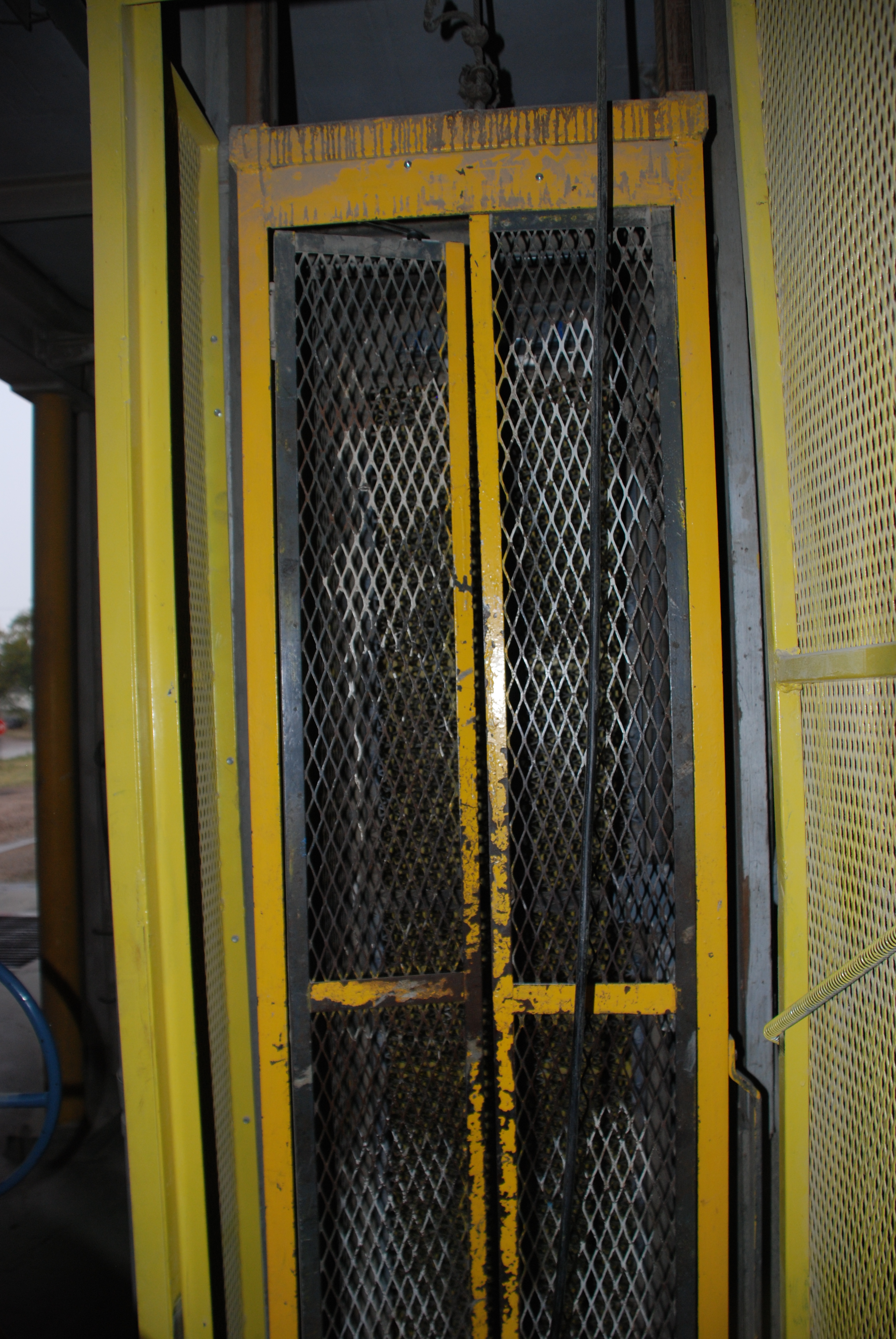
Number of legs: 1

Distributor floor: yes

Track sink: yes

Full basement: yes

Electrical room: yes

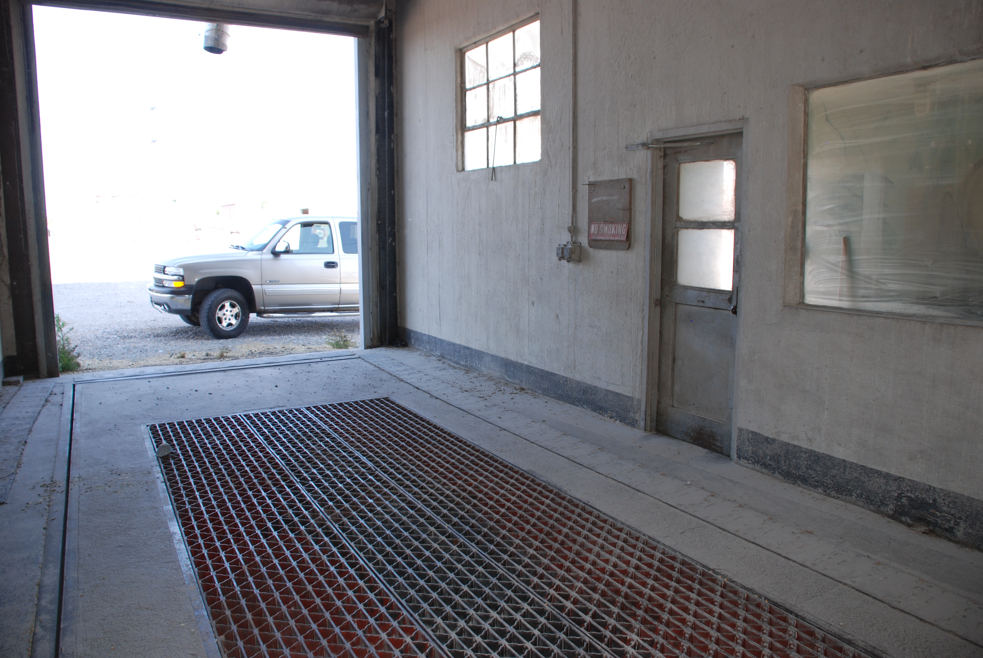
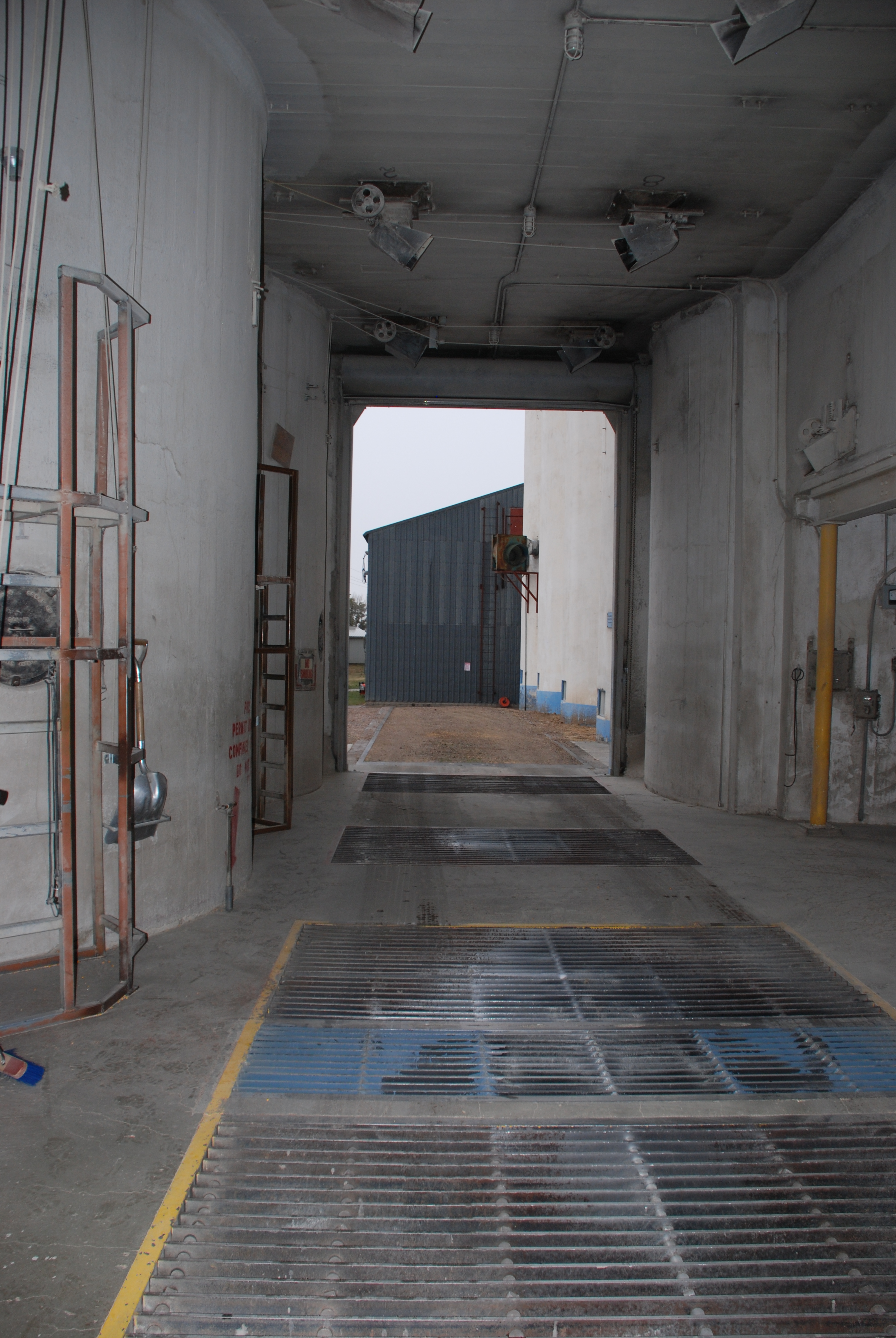
Driveway width clear: 13′

Dump grate size: 2 at 9′ x 5 1/2′ and 9′ x 15′

Column under tanks size: 16″ square

Boot legs and head: concrete

Machinery details

Boot pulley: 60″ x 14″ x 2 3/16″

Head pulley: 60″ x 14″ x 3 15/16″

R.P.M. Head pulley: 44

Belt: 272′, 14″ 6 ply Calumet

Cups: 12″ x 6″ at 9″ o. c. spacing

Head drive: Howell 30 horsepower [3 circled here]

Theoretical leg capacity (cup manufacturers rating): 6,540 bushels per hour

Actual leg capacity (80% of theoretical rating): 5,230 bushels per hour

Horsepower required for leg (based on above actual capacity plus 15% for motor): 19.9 horsepower

Man lift: 2 horsepower Ehr.

Load out scale: 10 Bu. Rich.

Load out spout: 8 1/4″ w.c.

Cupola spouting: 10″ diameter 14 ga.

Truck lift: 7 1/2 horsepower Ehr.

Dust collector system: Fan to bin

Driveway doors: 2 overhead rolling

Conveyor: None

Remarks

Split bin for dryer

Analysis of photos from Tillotson Construction’s job in Alta, Iowa


scan0020

By Charles J. Tillotson with photos from the Neil A. Lieb archive

The images from the Neil A. Lieb Archive are the best historical, phase-by-phase photos that I’ve seen yet. They give the layman a good concept of what actually takes place, from start to finish, in building a grain elevator.

A few comments I might add:

The excavation for the foundation began with dynamite.

Excavating the foundation began with a bang.

Neil writes about the use of dynamite during the excavation process. Dynamite was used for foundation excavation on many a job because of the deep frost. We even used it for cutting the foundation of the reinforced concrete garage we built on the old place in Omaha. We were young ’ns then, but still got to set (light) the fuses to a few charges.

I remember getting the neighbors excited about what the hell we were doin’ now.

By the way, the garage utilized slip-form construction with steel stays instead of wood for the formwork—another of Dad’s experiments. He was interested in finding materials that could be reused over and over, rather than having to buy lumber formwork for every new job. I guess this method didn’t make a lot of sense, as he never tried it out on an elevator.

scan0008

This photo is an historical testimony as to how the so-called unskilled, common man could be taught layout along with measuring, wood cutting, and other carpentry skills. The labor used to build these forms and construct the entire grain elevator structure was obtained, for the most part, from the inhabitants of the local vicinity where the elevator was to be built. Most of the workmen had no experience whatsoever in the construction industry.

scan0010

People used to marvel at how the cement went into the top of the formwork and came out the bottom of the forms, in a set-up, semi-solid state, all occurring whilst the deck and forms continued to extend upwards, being jacked up on screw jacks. Once the slipping of the forms began, it never stopped, unless by a power outage, a severe storm, or some other interference.

scan0014

Beneath the deck and main formwork, a sub-scaffolding was constructed to provide access to the exterior face of the concrete structure, which required patching and touch-up for a final smooth finish. A rich mixture of cement, sand, and lime was used which was applied to the concrete face by hand, usually covering the entire exterior surface, removing all blemishes. The finish material was hoisted in five-gallon buckets to the finishers. These workmen traversed the scaffold of wood planking—usually two, 2 x 12s laid flat between the wooden hanger frames that attached to the formwork above. Very dangerous work without a safety net!

At the ground level, a workman on a tractor would load a Georgia buggy with cement, to be hoisted to the top and placed in the formwork. Small skip loaders, tractors with scoop-type buckets mounted on the front, were an essential tool used during construction. This included scooping up the sand, gravel, and cement to make concrete and placing them in a mixer.

Neil A. Lieb collection Once the concrete was ready for placement, the tractor scoop was filled with the cementitous mixture and transported to the side of the elevator whereby the tractor would dump its load into a Georgia buggy to be hoisted up to the deck for placement.

Because of the extensive use of the tractor, more than one would be worn out. During the extremely active 1950s, Tillotson Construction Company would purchase Ford Ferguson tractors a dozen at a time, just to keep up with the need for replacement

The logistics of material supply was always challenging for the grain elevator builder. Usually, the projects were located in very rural farmland areas, where the supply of lumber, steel, sand, gravel, cement, gasoline, and oil was miles from the site. Because the construction utilized the slip-form method, the operation never stopped once it began, making it paramount that the supply of materials be established beforehand along with a comfort level that there would be no interruption once the job started.

Neil has noted (in an as yet unpublished commentary) the mixture of the gleaming, white, finished “paint,” which wasn’t really paint at all but instead a cementitious mixture that lasted for a very long time. Some of the elevators existing today still boast the original finish. Tillotson was among the few contractors that finished out their jobs this way.

scan0005

Training the local unskilled labor in the processes of placing and wire-tying the reinforcing steel –and of pouring concrete, turning screw jacks, keeping the slip-form deck level, et cetera– were just a few of the many headaches the job superintendent had to bear during the initial start-up phases.

A view of early preparations at the foundation of Alta Cooperative’s elevator

scan0003

Photo from the Neil A. Lieb Collection

In a July 22 telephone conversation, Neil A. Lieb, who worked for Tillotson Construction Company from 1949 to 1951, described for us the elements of this photo, taken in the spring of 1950 during the earliest stage of work on the Alta Cooperative elevator, in Alta, Iowa.

  • The slab and rebar box in middle is the pit, covered with wood to leave a hole in concrete.
  • The horizontal box in the background is for the elevator’s leg, the critical motor-driven pulley-and-belt mechanism with attached scoops that lift the grain from the pit to the headhouse for distribution to bins and silos.
  • Planking is to provide a smooth course for the wheelbarrow in order to transport and dump freshly mixed concrete.
  • The dirt in the background came from the excavation.
  • In the center, the larger black tank on left contains acetylene and the smaller one holds oxygen, for fueling a torch, presumably to cut rebar.
  • The concrete mixer (upper left) had the capacity of one-half or one cubic yard of concrete.

Editor’s note: Although there is some distortion, the upper-right corner appears to show a worker who is bent at the waist and leaning away from the camera.


Excavating with explosives led to trouble on Tillotson’s Alta, Iowa, elevator


scan0001

Story by Neil A. Lieb and photos from the Neil A. Lieb Collection

I do not know exactly when the Alta job started, but I think it was in March or early April of 1950. At that time of the year the ground in Iowa is frozen two to three feet deep. Since the ground was frozen, the bulldozer could not dig the hole needed for the slab. So it was decided they would use dynamite to loosen the soil. I guess Superintendent Bill Russell had this approved by the town fathers and the police and fire chef. 

Neil A. Lieb, left, and Blaine Bell worked on the Alta, Iowa, elevator in 1950.

Neil A. Lieb, left, and Blaine Bell worked on the Alta, Iowa, elevator in 1950.

Now, remember, Alta is a very small town, maybe 900 to 1000 residents then.

It was decided to use one-quarter stick of dynamite at a depth of 18 to 24 inches. The first charge was set off and it loosened about six to seven feet of dirt so they repeated this procedure every six to eight feet.

After setting off several charges, someone decided that if one-quarter stick worked so well, one-half stick would loosen a bigger area. So they used one-half  stick for the next charge. When it was set off, the explosion was so loud that Bill came charging out of his office to find why at about the same time as the woman across the street came out of her house screaming that her china cabinet had fallen over and all her good china had been broken. 

Within a few minutes the mayor, fire and police chiefs, and most of the town council members showed up. I guess Bill was very busy trying explain. Once he’d calmed everyone down, they all left.

That was the end of the dynamiting. The next day everyone was swinging a pick.

scan0007


Newly discovered photos show Tillotson’s big Alta, Iowa, grain elevator in 1950

Neil A. Lieb collection

Photos contributed by Neil A. Lieb

Of the slew of elevators Tillotson Construction Company put up in 1950, the one at Alta, Iowa, could have been considered a typical job, although the photo above shows that a sign company must have gone to work sinking anchors in the headhouse for the raised lettering. Built in the small Buena Vista County town that sits at the highest point on the Chicago-Illinois Railroad in its crossing of the Hawkeye State, the elevator followed Tillotson’s established Palmer Plan, with eight tanks of 18 feet in diameter rising to 115 feet in height. There was a 13-foot-wide driveway passing through the house in an opening 15 feet high under four split bins. An additional note about the Palmer plan says, “Extra dist @ Cupola and on Cleaner Floor,” and we take the abbreviation to mean distribution.

Formwork as the Alta Cooperative's elevator rises in a continuous pour. Note the driveway door.

Formwork as the Alta Cooperative’s elevator rises in a continuous pour. Note the driveway door.

Here is the full list of specifications:

Capacity per Plans (with Pack) 246,070 bushels

Capacity per foot of height 2640 bushels

Reinforced concrete/plans (Total) 2082 cubic yards

Plain concrete (hoppers) 49.6 cubic yards

Reinforcing steel/Plans (includes jack rods) 112.4 tons

Average steel per cubic yard of reinforced concrete 107/96 pounds

Steel & reinforced concrete itemized per plans

Below main slab 9419 lb/91 cu yd

Main slab 32,077 lb/272 cu yd

Drawform walls 142,070 lb/1424 cu yd

Work & driveway floor (including columns) 1485 lb/30 cu yd

Deep bin bottoms 6682 lb/47 cu yd

Overhead bin bottoms 7929 lb/40 cu yd

Bin roof (corner) 10150 lb/51 cu yd

Scale floor (complete) none

Cupola walls 9655 lb/88 cu yd

Distributor floor 1912 lb/10 cu yd

Cupola roof 2753 lb/15 cu yd

Miscellaneous (boot, leg, head, track sink, steps) 2560 lb/13 cu yd (a note here in the plans says “Cleaner floor”)

Elevator construction continued around the clock in a spectacle that must have awed the surrounding community.

Elevator construction continued around the clock in a spectacle that must have awed the community.

Construction details 

Main slab dimensions (Drive length first dimen.) 60 x 73.5 feet

Main slab area (actual outside on ground) 4101 sqare feet

Weight of reinforced (total) concrete (4000#/cu yd + steel) 4276 tons

Weight of plan concrete (hoppers 4000#/cu yd) 99 tons

Weight hopper fill sand (3000#/cu yd) 708 tons

Weight of grain (at 60# per bushel) 7380 tons

Weight of structural steel & machinery 20 tons

Gross weight loaded 12,483 tons

Bearing pressure 3.04 tons per sq ft

Main slab thickness 24 inches

Main slab steel (bent) 1 in diameter at 7 inch o.c.

Tank steel at bottom (round tanks) 5/8 inch diameter at 6 inch o.c.

Lineal feet of drawform walls 762 feet including exterior

Height of drawform walls 115 feet

Pit depth below main slab 15 feet 0 inches

Cupola dimensions (W x L x Ht.) 23 x 61.5 x 39 feet

Pulley centers 161 feet

Number of legs 1

Distributor floor Yes

Track sink Yes

Full basement Yes

Electrical room Yes

Driveway width–clear 13 feet

Dump grate size 3 – 9 x 6 feet

Columns under tanks size 20 inches square

Boot — leg & head Concrete

scan0010

Machinery Details 

Boot pulley 72 x 14 x 2 3/16 inches

Head pulley 72 x 14 x 3 15/16 inches

R.P.M. head pulley 42 rpm

Belt 14 inch 6 ply Calumet

Cups 12 x 6 inch at 8 inch o.c. Howell

Head drive 40 horsepower

Theoretical leg capacity (cup manufacturer rating) 8440 bushels per hour

Actual leg capacity (80 percent of theoretical) 6750 bushels per hour

The finished elevator, before the headhouse windows were installed and whitewashing was done.

The finished elevator, before whitewashing and installation of the headhouse windows.

Horsepower required for leg (based on above actual capacity plus 15 percent for motor) 33 hp

Man lift 1.5 horsepower electric

Load out scale Two 25 bushel Rich.

Load out spout 10.75 inch W.C.

Cupola spouting 10-inch diameter 14 gauge

Truck lift 7.5 horsepower Ehr

Dust collector system Fan → Dust bin

Driveway doors Two overhead rolling

Conveyor 14-inch R.H. 3 hp.

A Tillotson elevator overlooks the 76th Dayton Championship Rodeo grounds

DSC_0591

The Dayton, Iowa, rodeo grounds bustle with activity for the championship event.

Story and photos by Kristen Cart

The Dayton, Iowa, elevator is an especially handsome one, built in a typical Tillotson style. It is one of an overwhelming majority of Tillotson elevators that are still in use. It is quite an achievement to build something so enduring.

DSC_0566

Modern updates are evident in this view.

One of the secrets of the longevity of concrete elevators of this type is the ability to upgrade the machinery and to expand capacity. The elevators were built with the understanding that they would soon be filled and would need additional bins. The Tillotson Construction Company revisited certain sites over and over as they added concrete annexes and other improvements, while occasionally other companies won the contracts.

DSC_0579

The feed mill stands to the right.

You can see that the concrete elevator was retrofitted with an external leg. This modification is a safer design than the old internal one, because accumulated grain dust cannot come into contact with overheated machinery if a bearing or belt fails. Metal bins were added for additional capacity. A feed mill complements the storage facility, completing a one-stop shop for farmers.

The Dayton elevator’s original construction was not without trouble, however. Tillotson Construction Company was compelled to pay for repairs after the elevator cracked under its original grain load. The Farmers Elevator Company sued, according to the Farmers Elevator Guide, in 1954. The repairs were expertly done and the elevator still stands today.

A photographic review of concrete elevator parts and components

Story and photos by Kristen Cart

Some time ago, one of our readers requested the picture of an elevator pit. It is one of the more unglamorous parts of a grain elevator, but as I was going through old photos, I found one. I also found many interior elevator pictures that have not made it to the blog because of their, well, unattractiveness. But a review of the parts and pieces, terms and descriptions, and interior appearance of an elevator is in order.

 The Pit

Pit access by ladder. The leg is visible.

Pit access by ladder. The leg is visible. Hanover, Kan.

DSC_0677(2)

Sloped bottom funnels grain to the base of the leg.

The Dump Grate

DSC_0674(2)

A smaller grate.

DSC_0292(1)

Center driveway truck grates.

The Driveway

DSC_0410

McCook, Neb.

DSC_0208(1)

St. Francis, Kan.

The Man Lift

DSC_0679(1)

The bottom of the lift showing the shaft.

DSC_0210(1)

Current safety regulations require a retrofitted cage.

Overhead bin spouts

Bins are numbered to correspond with the bin diagram

Bin Diagram

St. Francis, Kan.

St. Francis, Kan.

DSC_0295

This elevator holds beans in two overhead bins.

DSC_0670(1)

The bins hold milo, and “F” means the bin is full.

The Leg

DSC_0418

Cup dimensions and spacing are given in elevator specifications.

DSC_0673(1)

The leg conveys grain from the pit to the top of the bins.

Manhole Cover

Traer, Kan.

Traer, Kan.


Insights from a Ralston, Iowa, elevator maintenance worker

DSC_5966

At the far left edge of the photo, the annex can be seen behind the similarly sized elevator.

Story and photos by Kristen Cart

Each time we travel to Nebraska to see our family, I try to investigate elevators, and the kids groan and roll their eyes, pulling electronic entertainment out of their backpacks.

In March, our trip home warranted a stop at Ralston, Iowa, where we hoped to see an annex built by Tillotson Construction Company of Omaha as we trekked eastbound along U.S. Highway 30. Ralston is about midway across the state and lies south of the highway, and is the site of one of the projects documented in Tillotson company records.

The West Central Cooperative elevator complex, silent and lofty, rimmed the edge of town as we approached on a bright Sunday afternoon. Not a soul was in sight as we entered the parking lot near the cooperative headquarters. But a car in front of the office building was open with a shopvac beside it. Someone had to be around.

DSC_6016

A much larger group of elevators was behind me, away from the town, as I took the photo.

The elevator group in Ralston is dominated by a large squarish elevator, a multi-bin elevator, and a large, multi-bin, rectangular annex snugged in beside the latter. Between the first elevator and the second is an old wood elevator which immediately attracted my attention. It made a fine photographic subject. While shooting the scene, I looked for signs of a Tillotson project. Nowhere was there any manhole cover with the name of a builder. And no one was present who could give me a look inside.

The annex, slightly narrow than the elevator, is on the left

The annex, slightly narrower than the elevator, is on the left.

In fact, the deserted elevator group so dominated the town, along with its companion group of elevators a mile or so down the tracks, that it seemed intimidating to go near it. So I stood off and took photos from across the street.

DSC_6001Heavy rail traffic attended the tracks alongside the elevators in spite of the sleepy Sunday. I counted several trains, blaring their arrival as they passed through town.

At last, a fellow emerged from the cooperative building and commenced vacuuming the company car. I approached him to ask him about the elevators. Ron Hickey, of Farnhamville, Iowa, waved a friendly greeting. He said he was a bit of a newcomer to the Ralston site, but had worked at Boxholm, Iowa, the site of another Tillotson elevator, for two years before coming here. He said that Boxholm’s elevator had 96 florescent light bulbs, and until recently, he was responsible for cleaning every one of them.

Presently, he was cleaning one of several company vehicles parked in front of the nicely appointed offices. The place had every sign of prosperity. Ron said West Central was one of the largest cooperatives in Iowa, and was very successful.

Once we arrived home, I had to resort to the company records to positively identify Tillotson Construction’s contribution to the site. The specifications for Ralston fit the size of the annex I had seen–a massive structure about twice the size of the average elevator project. Since this structure was an annex, many items normally included in a complete elevator build were not required. The Tillotson construction details are reproduced below.

The Ralston storage was built in 1953 using the “Ralston Plan,” which had eight 28′ diameter, 115′ tall bins with a 2′ spread, flat bottoms, and a screw conveyor.

Capacity per plans: 537,000 bushels

Capacity per foot of height: 4,838 bushels

Reinforced concrete per plans (total): 2,779 cubic yards

Plain concrete (4″ hoppers and liner): 9 cubic yards

Reinforcing steel per plans (includes jack rods): 168.18 tons

Average steel per cubic yard of reinforced concrete: 121.00 lbs.

Steel and reinforced concrete itemized per plans

Below main slab: steel 3,128 lbs.; concrete 29 cubic yards

Main slab: steel 102,340 lbs.; concrete 606 cubic yards

Draw form walls: steel 203,034 lbs.; concrete 1,920 cubic yards

Driveway and work floor: not installed

Deep bin bottoms: not installed

Overhead bin bottoms: steel 4,666 lbs.; concrete 24 cubic yards

Bin roofs and extension roofs: steel 14,284 lbs.; concrete 112 cubic yards

Cupola walls: steel 8,907 lbs.; concrete 20 cubic yards

Distributor floor: concrete 2 cubic yards (steel included in above total)

Cupola roof: concrete 3 cubic yards (steel included in above total)

Miscellaneous (boot, leg, head, track sink, steps, etc.): not installed

Attached driveway (in this plan, a gallery, with cross tunnel not included): concrete 63 cubic yards (steel included in above total)

DSC_6010Construction details

Main slab dimensions: 66 2/3′ x 121 2/3′

Main slab area (actual outside on ground): 7,738 square feet

Weight reinforced concrete (4,000 lbs. per cubic yard plus steel): 5,726 tons

Weight plain concrete (4,000 lbs. per cubic yard): 18 tons

Weight hopper fill sand (3,000 lbs. per cubic yard): 154 tons

Weight of grain (60 lbs. per bushel): 16,125 tons

Weight structural steel and machinery: 20 tons

Gross weight loaded: 22,043 tons

Bearing pressure: 2.86 tons per square foot

Main slab thickness: 24 inches

Main slab steel (size and spacing): straight; 1 1/4 square inches and 8 inches o. c.

Tank steel and bottom (round tanks): 5/8 inch diameter and 6 inches

Lineal feet of draw form walls and extension: 717 feet 7 inches; 39 feet 6 inches

Height of draw form walls: 115 feet

Pit depth below main slab: 9 feet 6 inches

Cupola dimensions (outside width and length and height): 12′ x 14′ x 20′

Pulley centers: 137 1/2 feet

Number of legs: 1 main (see pulley center above) and 1 jack

Distributor flow: yes

Track sink: no

Full basement: no

Electrical room: no.

Driveway width-clear: not installed

Dump grate-size: not installed

Columns under tanks: not installed

Boot–leg and head: steel

Machinery details

Head pulley (main leg): 48″ x 16″ x 4 15/16″

Boot pulley: 48″ x 13″ x 2 3/16″

RPM head pulley: 48 rpm

Belt: 15″-6 ply calumet

Cups: 14″ x 7″ at 10″

Head drive: Howell 40 horsepower: 3

Theoretical leg capacity (cup manufacturer’s rating): 7,950 bushels per hour

Actual leg capacity (80% of theoretical): 6,350 bushels per hour

Horsepower required for leg (based on above actual capacity): 26.4 horsepower

Man lift: not installed

Load out scale: not installed

Load out spout: not installed

Truck lift: not installed

Dust collector system: fan into bin

Cupola spouting: not installed

Driveway doors: not installed

Conveyor: 24 inch screws

Also built

Track scale: 50 foot, 50 ton: concrete 35 cubic yards


The Tillotson elevator in Lincoln, Nebraska is majestic in winter light

DSC_3138Story and photos by Kristen Cart

One of the most beautiful projects completed by Tillotson Construction of Omaha was their elevator with its annex in Lincoln, Neb. I was fortunate to be able to persuade my dad to stop with me to take some photos in perfect light.

DSC_3174One of the challenges of elevator photography is picking the structure out from its sometimes tight surroundings.

Usually you can take close pictures with a wide angle lens, which distorts straight lines, but can give you a full view of the elevator. In this case, I was without that tool since it broke when it fell off a chair, so I had to make do with a mid-range zoom lens.

You be the judge of whether the pictures were successful, given the limitations of distance, obstructions, and points of view.

DSC_3184

The trademark rounded headhouse rises above one of the largest elevators Tillotson Construction built

This elevator is a couple of blocks from the Cornhusker Highway in Lincoln, and one of the obstructions to a clear shot is an overpass feeding traffic to that main artery through town. The limited view required some cropping of the elevator. But the light and sky made up for the field of view.

The manhole covers display the company name on both the elevator and the annex

The manhole covers display the company name on both the elevator and the annex

We do not know why the Lincoln elevator is not among the projects recorded in the company ledgers. It appears that at least one page was missing from the records, and there is no way to know where it is, or why it is missing. So the only information we have about its construction is from the manhole cover on the main elevator, which says 1955. Presumably, the annex was built shortly thereafter.

Because the facility, AGP Grain Cooperative, was closed, we obtained no further details on this visit. This elevator will be the first on our list when the harvest time comes around again, and we can see the elevator in operation for ourselves.

Christmas ideas for an elevator enthusiast

DSC_0075Story and photo by Kristen Cart

Our good friend Linda Laird shares our interest in American grain elevators and has devoted much of her time to documenting these historic landmarks of the plains. I purchased her book some time ago and found it very enlightening. She did a terrific job. This book is on my short list of recommendations for Christmas, if you have an elevator lover on your list.

The American Grain Elevator

Another good friend and fine photographer Bruce Selyem, and his wife and excellent writer Barbara Selyem, have published several books on the subject of grain elevators, and they also publish an annual grain elevator calendar. Last time I checked they still had a few for sale. They also have fine prints for sale if you find an image of an elevator you can’t live without. I spend time on their site while planning elevator trips because of their extensive coverage of elevators all over the country and in Canada.

Grain Elevator Photos

Lastly, it is always a good idea to visit Gary Rich’s elevator photo pages to see his latest elevator photography. He recently finished a trip to Oklahoma, so I expect to see new images from there soon. He says he loves taking pictures in the winter sunshine, which is the perfect illumination for his subjects.

Gary Rich Grain Elevators

Enjoy the season!