A chance encounter with a Tillotson elevator in Jamestown, Kansas

DSC_0057

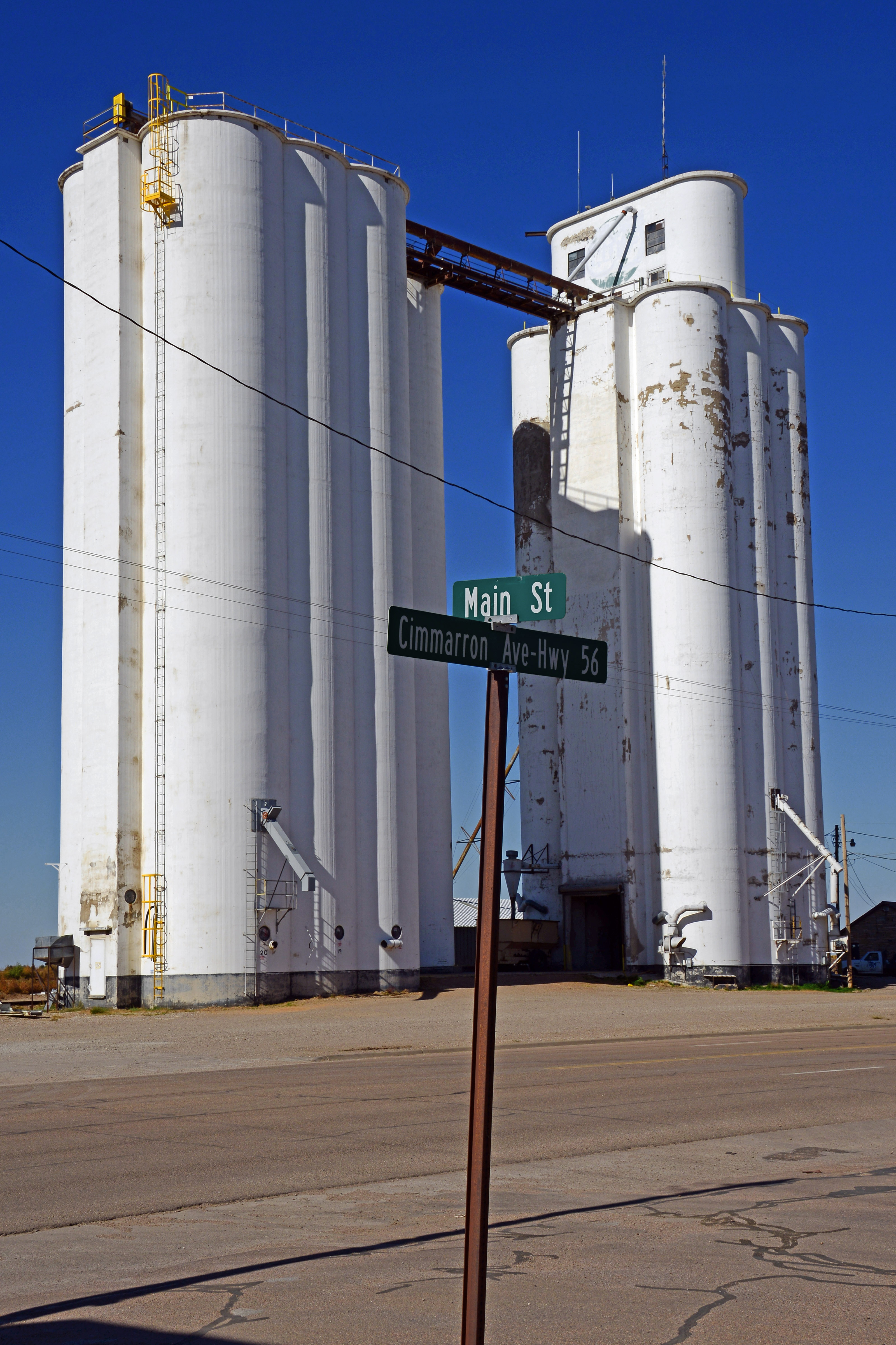
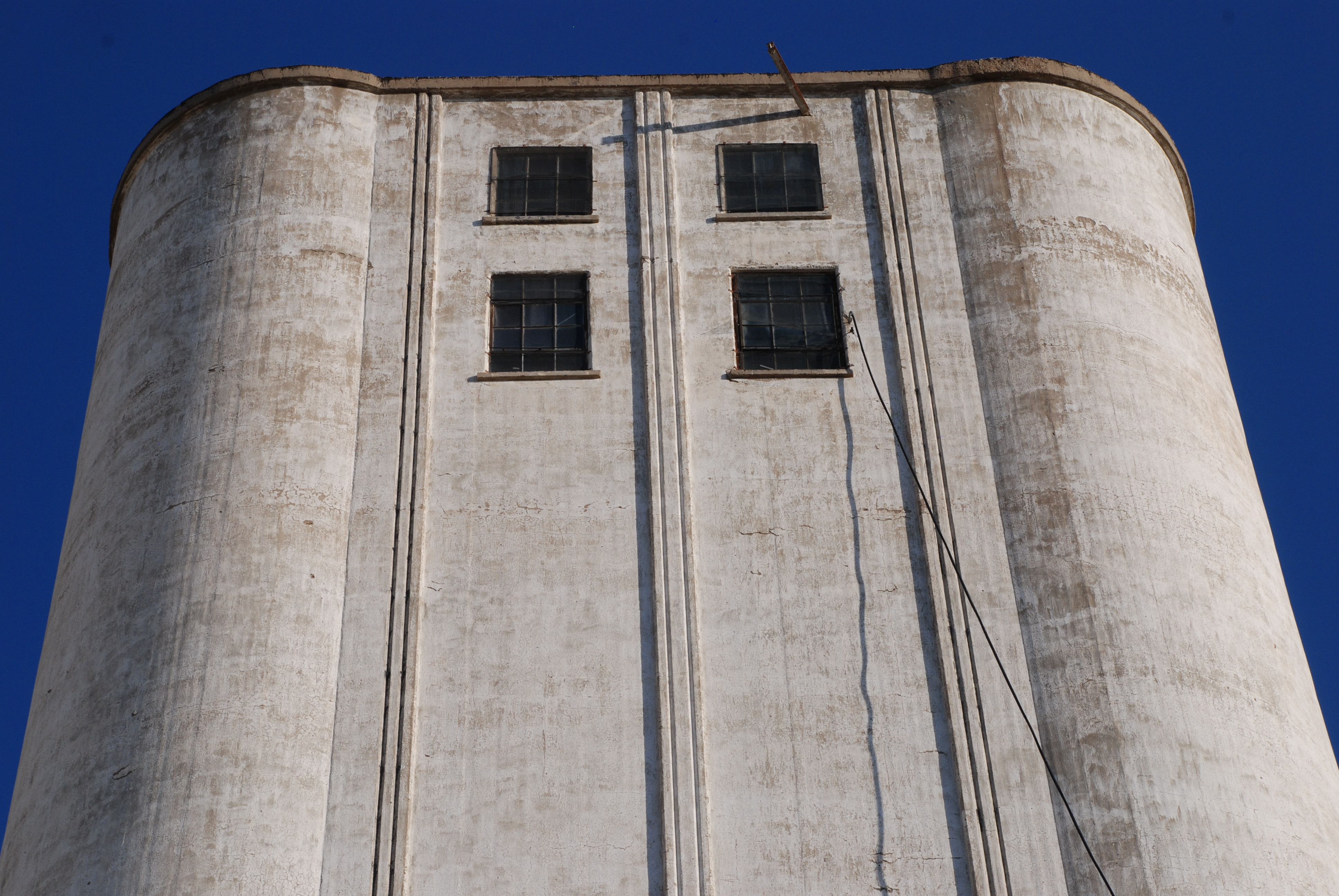
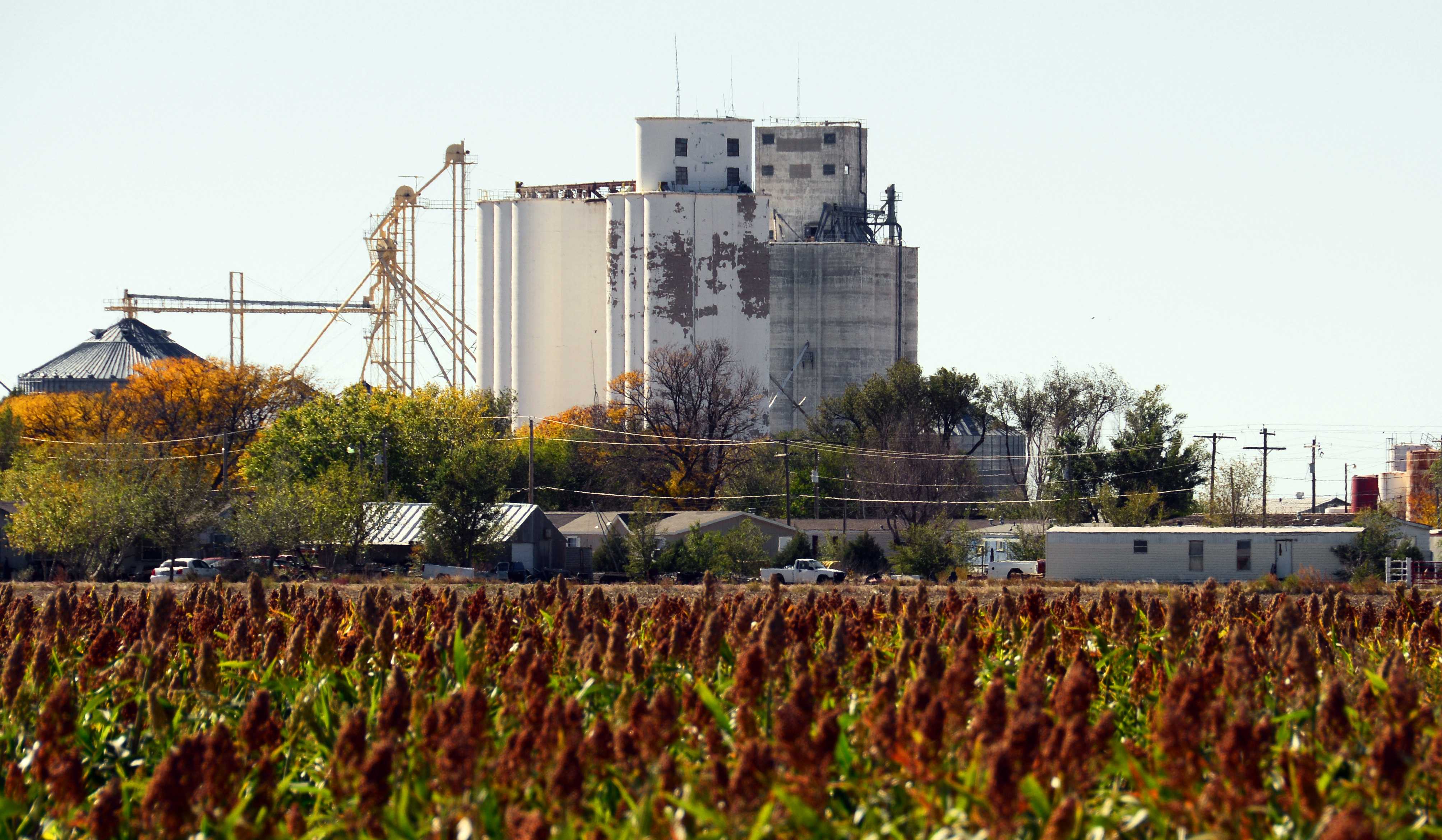
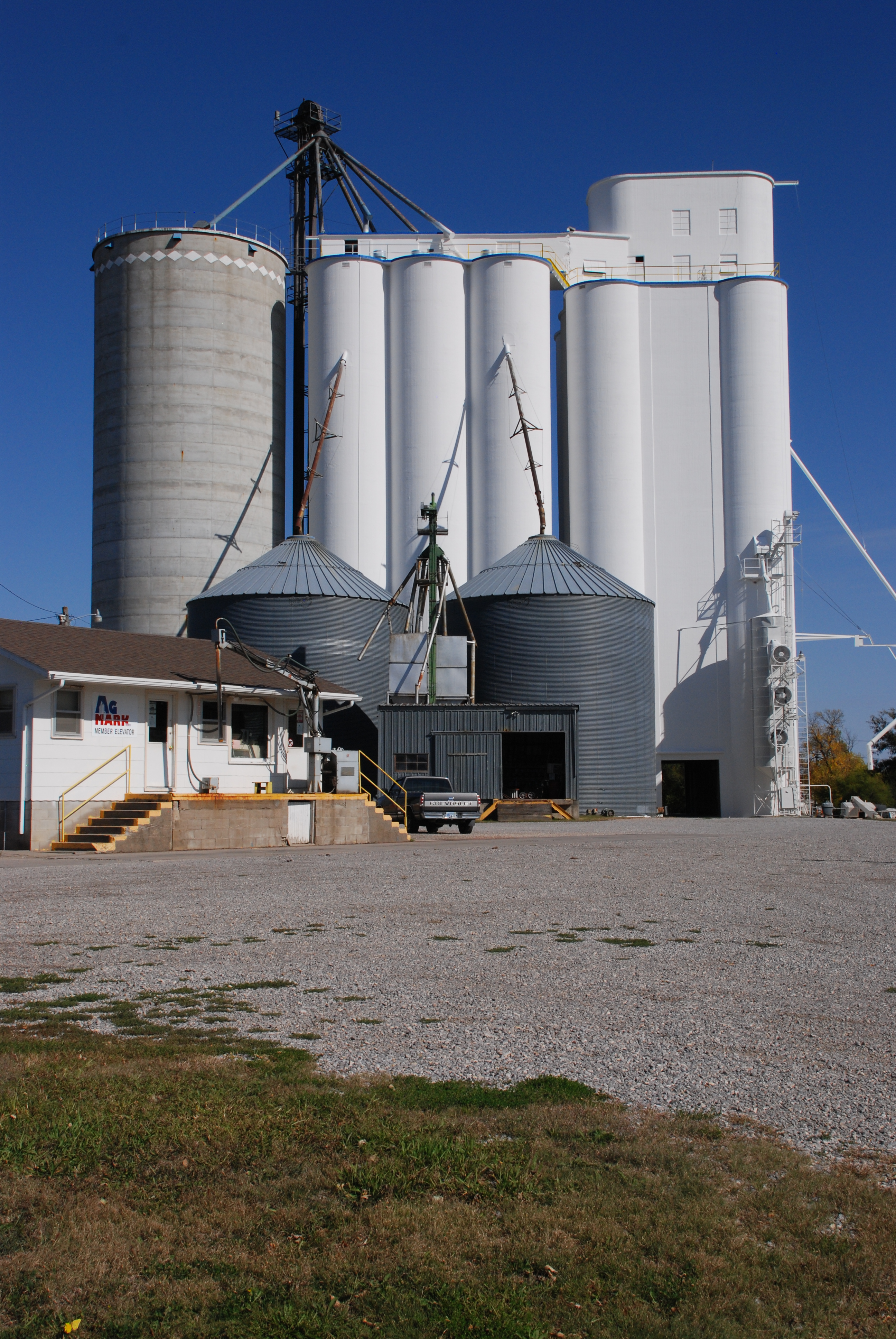
Sporting a fresh coat of paint, the trademark Tillotson elevator with its curved headhouse still operates. 

Story and photos by Kristen Cart

On our last elevator road trip, which our family embarked upon in October 2012, we visited many of our grandfathers’ elevator projects from the 1940s and 50s. But we also amassed a photo collection of elevators we could not place. Either the grain cooperatives were closed for business on a Sunday, or the elevators were retired, or we didn’t have time to stop for an interview. So the photos languished for most of a year, until Ronald Ahrens and I could identify them, even though we strongly suspected that the structures were the works of one of our grandfathers.

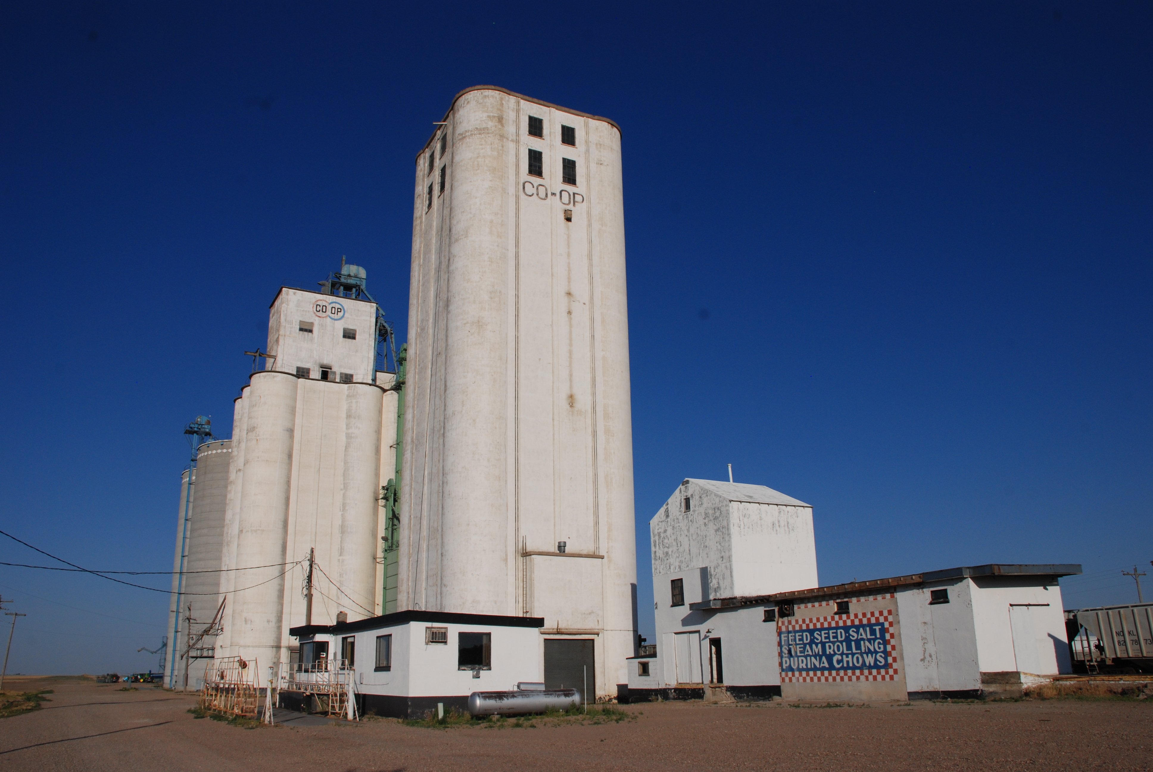
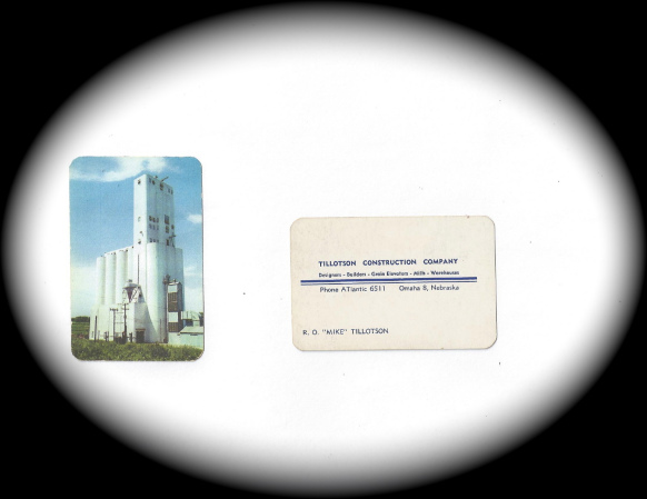
One of the mystery elevators was a pure white example, located in the north-central Kansas town of Jamestown. Ronald’s uncle, Tim Tillotson, recently handed us the Omaha builder’s construction specifications, which finally identified this handsome elevator as a project built in 1953 by the Tillotson Construction Company.

A smaller elevator stands on a branch of the rail line. It's builder is unknown.

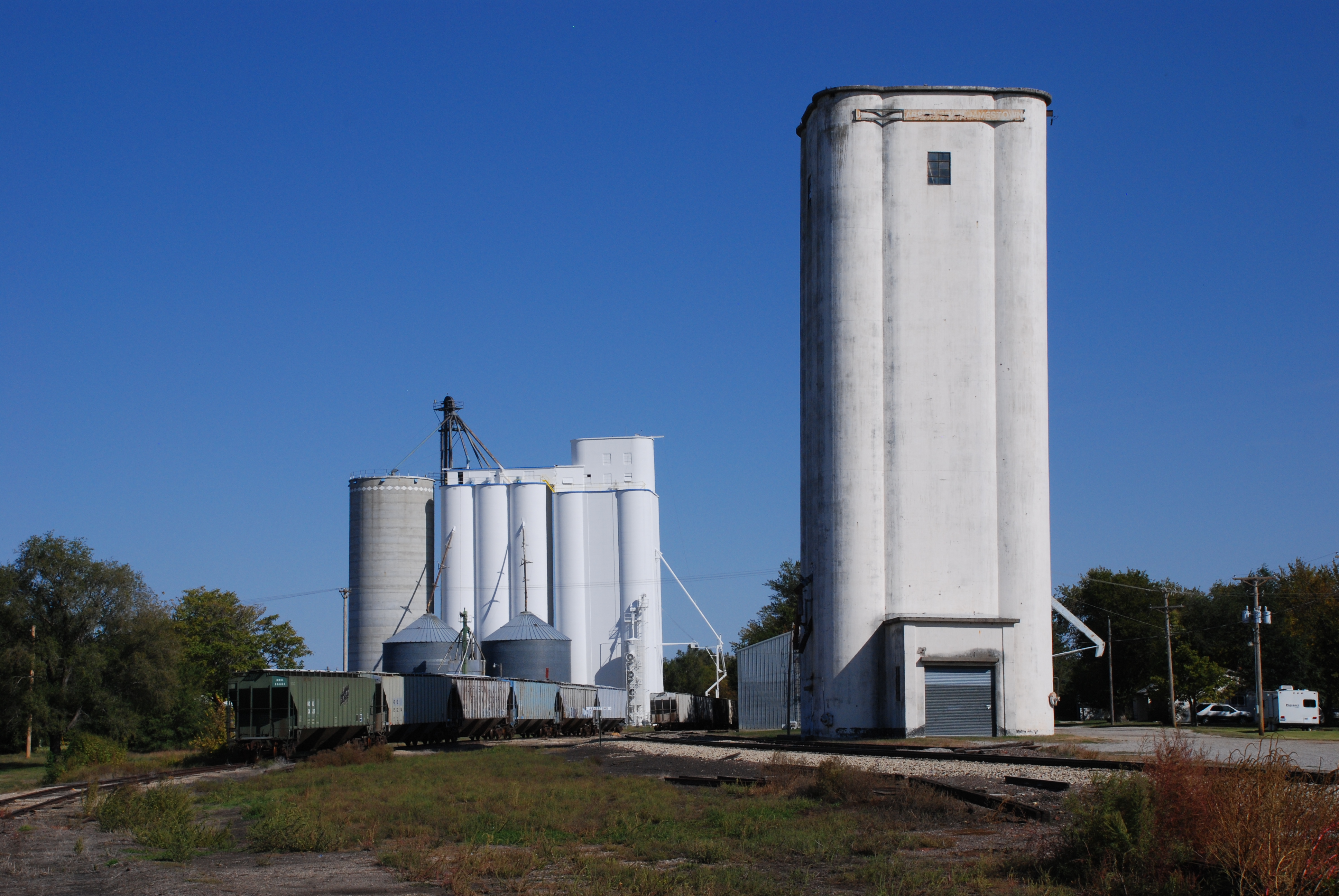
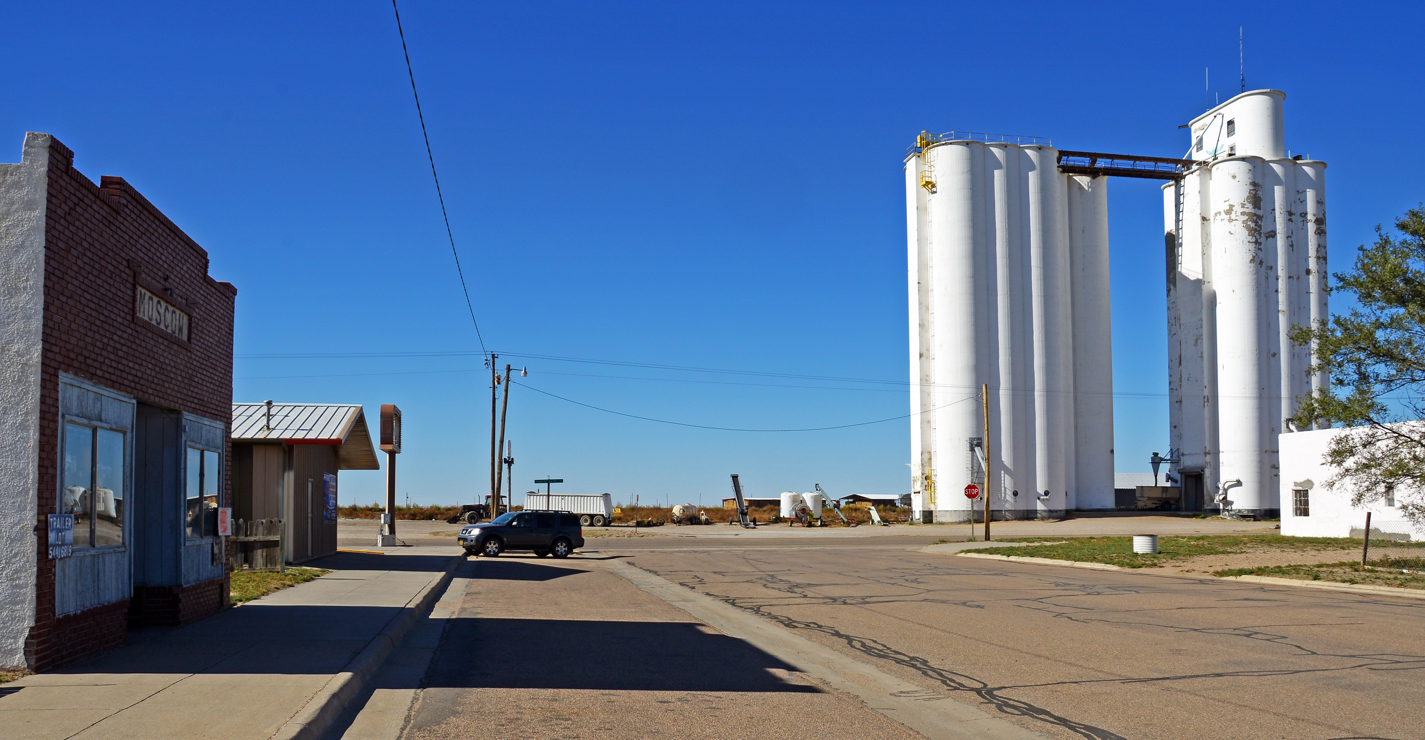
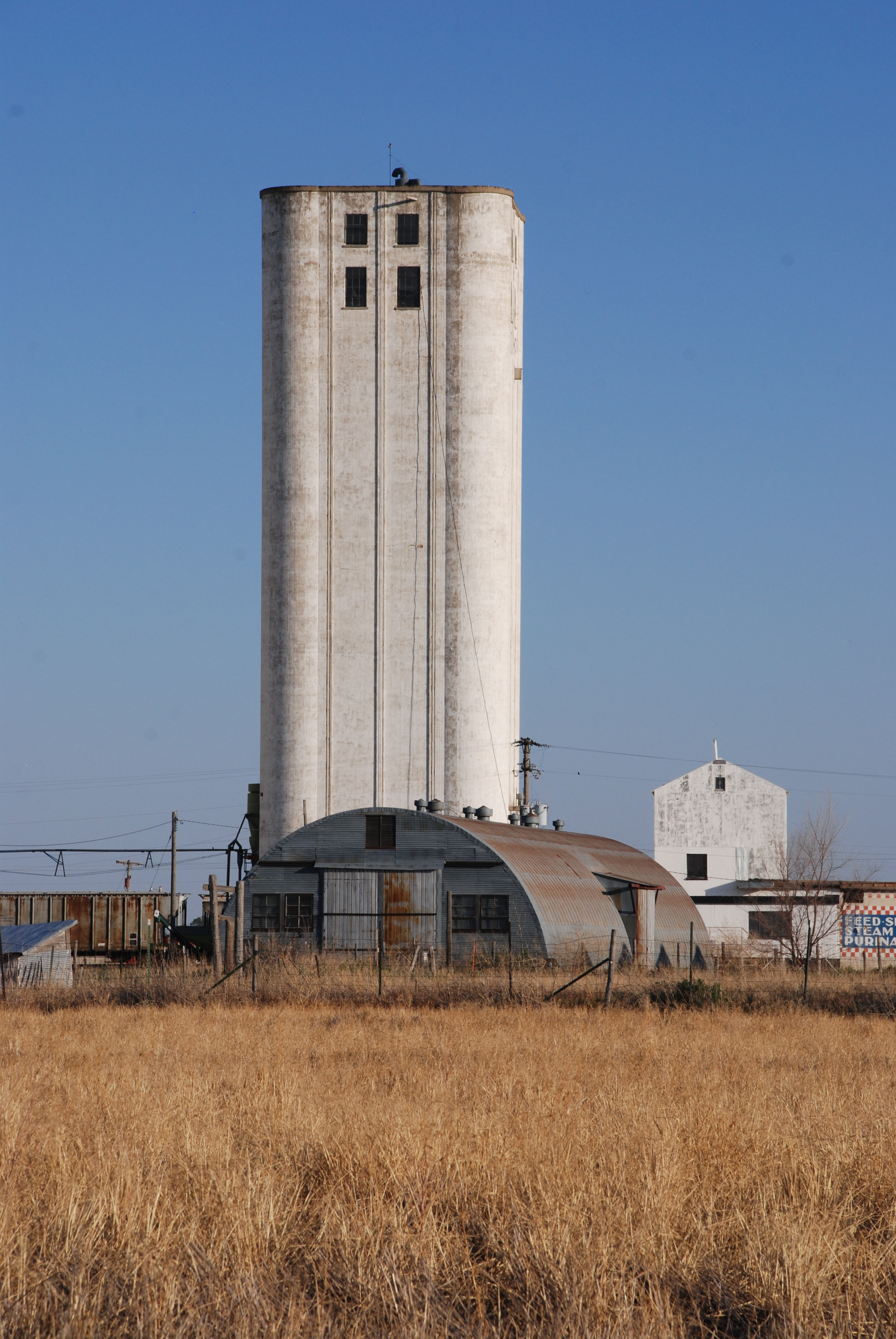
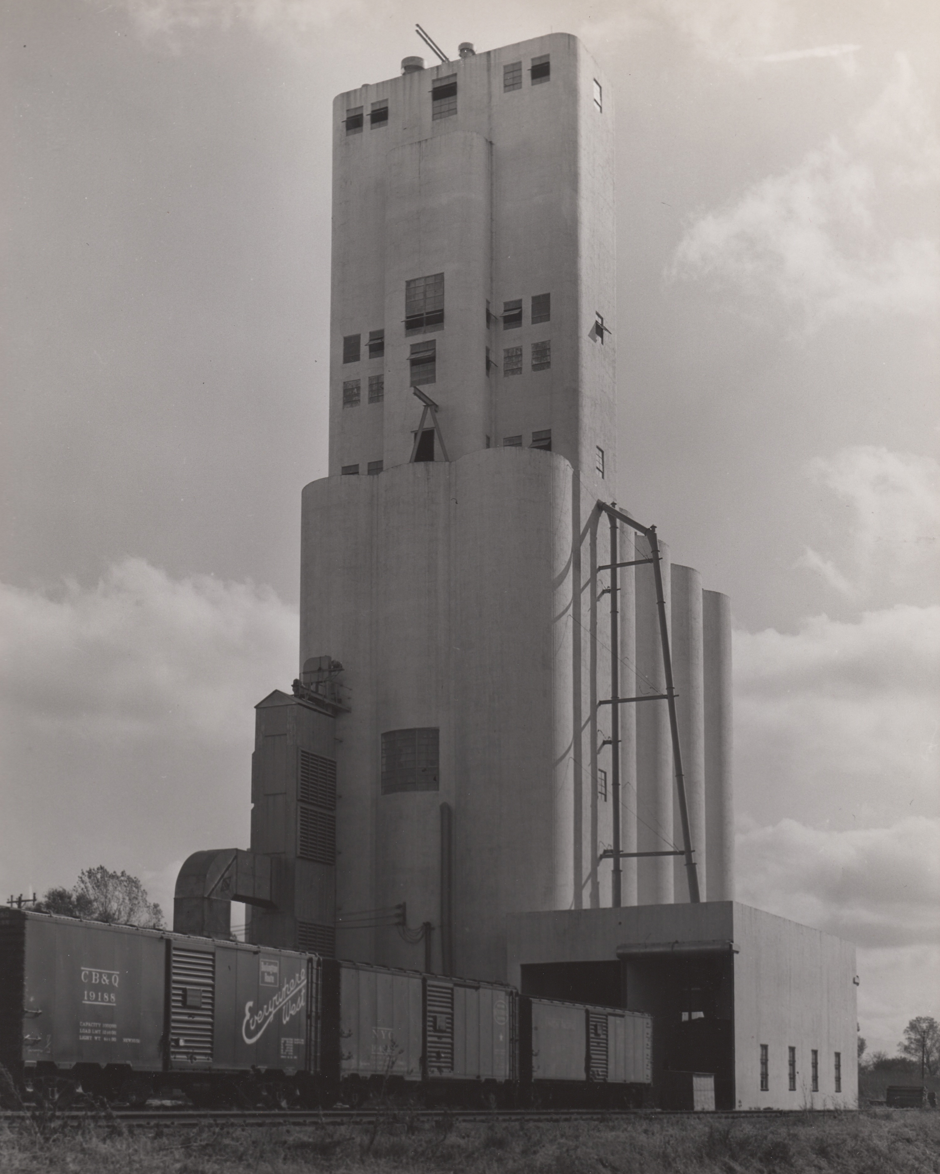
A smaller elevator stands on a branch of the rail line. It’s builder is unknown.

The Jamestown elevator stands not far from a companion elevator, rising alone on a fork of the railroad track. The smaller elevator was built in a straight-up style that predates the more common Tillotson style, and it’s provenance is unknown. It is reminiscent of the style of the elevator built by Tillotson Construction in Greenwood, Neb., but without the curved headhouse. But it also recalls several Chalmers and Borton examples.

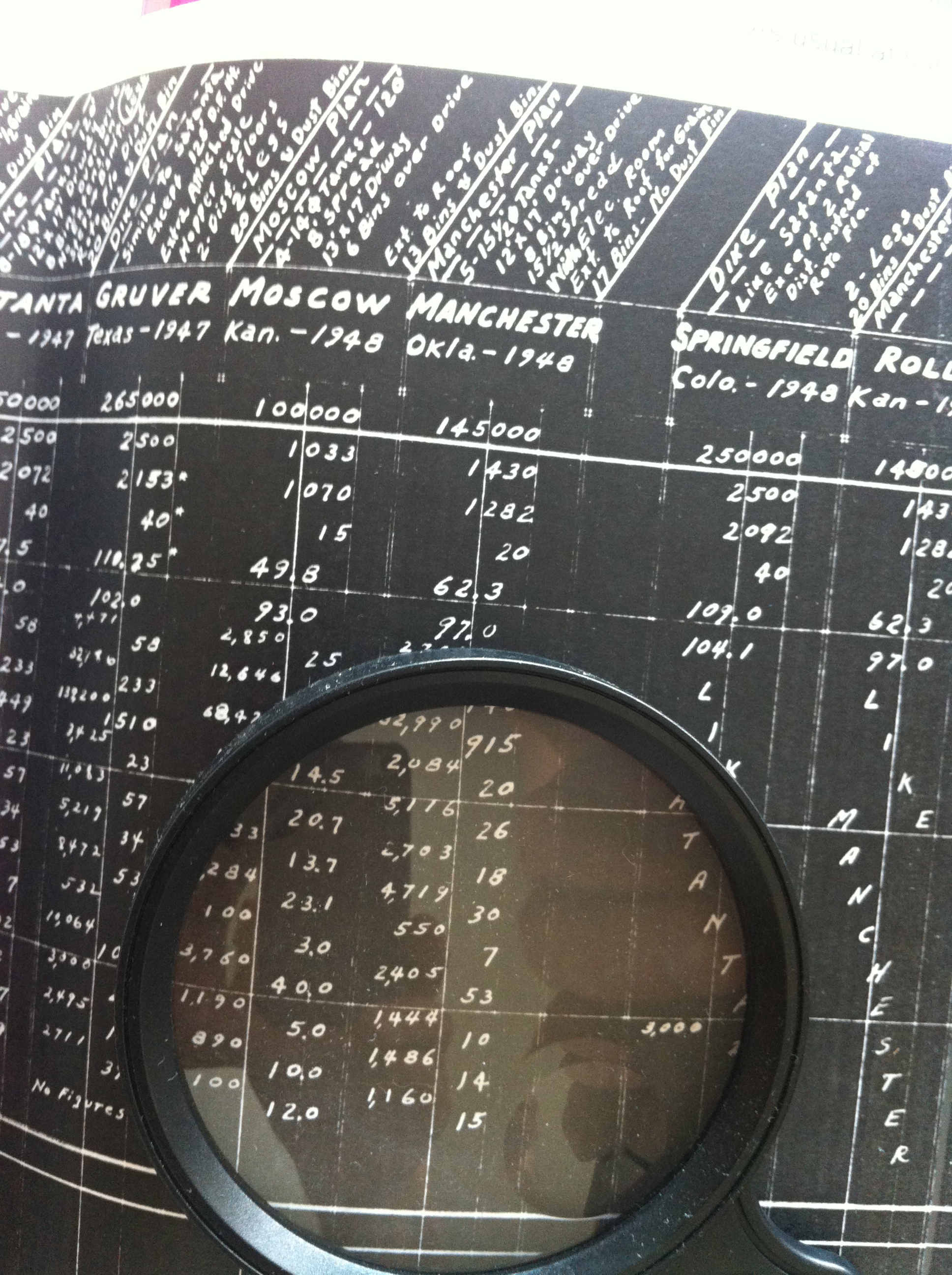
It is our good fortune to have the detailed specifications for the Jamestown elevator. Thanks to the Tillotson Company’s meticulous record keeping and the decades-long survival of the records, we can share the construction details of this remarkable structure. The specifications, for the engineering-minded among our readers, are presented below.

Capacity per Plans (with Pack) 155,320 bushels

Capacity per foot of height 1581 bushels

Reinforced concrete/plans (Total) 1530 cubic yards

Plain concrete (hoppers & liner) 17 cubic yards

Reinforced steel/Plans (includes jack rods) 69.38 tons

Average steel per cubic yard of reinforced concrete 90.6 pounds


Steel & reinforced concrete itemized per plans

Below main slab 4260 lb/52 cu yd

Main slab 19,427 lb/160 cu yd

Drawform walls 89,400 lb/1107 cu yd

Work & driveway floor (including columns) 1997 lb/18.5 cu yd

Deep bin bottoms 5236 lb/28.5 cu yd

Overhead bin bottoms 3175 lb/24 cu yd

Bin roof & extended roofs (or corner) 5139 lb/37.4 cu yd

Scale floor (complete) 292 lb/4.8 cu yd

Cupola walls 4897 lb/52.5 cu yd

Distributor floor 1530 lb/11 cu yd

Cupola roof 2207 lb/14 cu yd

Miscellaneous (boot, leg, head, track sink, steps, etc.) 1205 lb/20.3 cu yd (excluding track scale)

(At the head of the column on the next page, the Jamestown elevator was described thus: “Clifton Imo plan; Like Meno but split dust bin for Bin #17”)


Construction details

Main slab dimensions (Drive length first dimen.) 54 x 51 feet

Main slab area (actual outside on ground) 2625 square feet

Weight of reinforced (total) concrete (4000#/cu yd + steel) 3130 tons

Weight of plain concrete (4000#/cu yd) 34 tons

Weight hopper fill sand (3000#/cu yd) 684 tons

Weight of grain (at 60# per bushel) 4660 tons

Weight of structural steel & machinery 18 tons

Gross weight loaded 8526 tons

Bearing pressure 3.25 tons per sq ft

Main slab thickness 21 inches

Main slab steel (bent) 1 in diameter at 7 inch o.c.

Tank steel at bottom (round tanks) 0.5 inch diameter at 12 inch o.c.

Lineal feet of drawform walls 514 feet including exterior

Height of drawform walls 120 feet

Pit depth below main slab 15 feet 9 inches

Cupola dimensions (outside W x L x Ht.) 22.25 x 42.5 x 26 feet

Pulley centers 152.66 feet

Number of legs 1

Distributor floor Yes

Track sink Yes

Full basement Yes

Electrical room Yes

Driveway width–clear 13 feet

Dump grate size 2 @ 9 feet wide

Columns under tanks size 16 inches square

Boot — leg & head Concrete

(The remaining specs were noted “same as Meno.” The Meno specifications are given below.)

Machinery Details

Head pulley 72 x 14 x 4 7/16 inches

Boot pulley 72 x 14 x 2 3/16 inches

R.P.M. head pulley 42 rpm

Belt 14 inch 6 ply Calumet

Cups 12 x 6 inch at 9 inch o.c. Howell

Head drive 40 horsepower

Theoretical leg capacity (cup manufacturer rating) 7500 bushels per hour

Actual leg capacity (80 percent of theoretical) 6000 bushels per hour

Horsepower required for leg (based on above actual capacity plus 15 percent for motor) 27.75 hp

Man lift 1.5 horsepower Ehr

Load out scale 10 bushel Rich

Load out spout 10 inch W.C.

Truck lift 7.5 horsepower Ehr.

Cupola spouting 8.25 inch W.C.

Truck lift 7.5 horsepower Ehr

Dust collector system Fan → Bin

Cupola Spouting 10 inch W.C.

Driveway doors Two overhead rolling

Conveyor Not required

(Items below were listed for Meno; it is not clear whether these were also built at Jamestown)


Also Built

60 foot 50 ton scale: 40 cu yd

2 sk’ing spts (scaffolding supports?)

Full specifications of Tillotson Construction’s elevator in Moscow, Kansas

The construction record was written with painstaking attention to detail.

The construction record was written with painstaking attention to detail.

Our friend Linda Laird has asked if the Tillotson Construction Company’s records included any Kansas elevators. The answer is yes, and here’s an example.

In 1948, Tillotson built an elevator of reinforced concrete at Moscow, in the extreme southwestern corner of the Sunflower State. The plan’s basic aspects were as follows: four tanks of 14 feet in diameter, 120 feet in height, and an eight-foot spread. The driveway was was 13 x 17 feet and there were six bins over the drive. Another notation says “Ext. to roof.” This shows up on most other plans and is supplemented by “1/2 grain” or “for grain.” The final item at the head of the plan’s entry in company records notes “13 bins & dust bin.”  Here are all the data:

Capacity per Plans (with Pack) 100,000 bushels

Capacity per foot of height 1033 bushels

Reinforced concrete/plans (Total) 1070 cubic yards

Plain concrete (hoppers) 15 cubic yards

Reinforced steel/Plans (includes jack rods) 49.8 tons

Average steel per cubic yard of reinforced concrete 93.0 pounds


Steel & reinforced concrete itemized per plans

Below main slab 2850 lb/25 cu yd

Main slab 12,646 lb/91 cu yd

Drawform walls 68,424 lb/812 cu yd

Work & driveway floor (including columns) 1790 lb/14.5 cu yd

Deep bin bottoms 3740 lb/20.7 cu yd

Overhead bin bottoms 1733 lb/13.7 cu yd

Bin roof (corner) 2284 lb/23.1 cu yd

Scale floor (complete) 100 lb/3.0 cu yd

Cupola walls 3750 lb/40.0 cu yd

Distributor floor 1190 lb/5.0 cu yd

Cupola roof 890 lb/10.0 cu yd

Miscellaneous (boot, leg, head, track sink, steps) 100 lb/12.0 cu yd

Construction details 

Tillotson's Moscow, Kan., elevator, right, was built in 1948. The annex had to come later. Photo by Kristen Cart.

Tillotson’s Moscow, Kan., elevator, right, was built in 1948. The annex had to come later. Photo by Gary Rich.

Main slab dimensions (Drive length first dimen.) 40 x 45 feet

Main slab area (actual outside on ground) 1712 sqare feet

Weight of reinforced (total) concrete (4000#/cu yd + steel) 2190 tons

Weight of plan concrete (hoppers 4000#/cu yd) 30 tons

Weight hopper fill sand (3000#/cu yd) 260 tons

Weight of grain (at 60# per bushel) 3000 tons

Weight of structural steel & machinery 10 tons

Gross weight loaded 5490 tons

Bearing pressure 3.21 tons per sq ft

Main slab thickness 18 inches

Main slab steel (straight) 1 in diameter at 6 inch o.c.

Tank steel at bottom (round tanks) ⅜ inch diameter at 9 inch o.c.

Lineal feet of drawform walls 382 feet including exterior

Height of drawform walls 120 feet

Pit depth below main slab 11 feet 0 inches

Cupola dimensions (W x L x Ht.) 14 x 36 x 23 feet

Pulley centers 145.5 feet

Number of legs 1

Distributor floor Yes

Track sink Yes

Full basement Yes

Electrical room Yes

Driveway width–clear 12 feet

Dump grate size 2 – 6 x 11 feet

Columns under tanks size 20 inches square

Boot — leg & head Concrete


Machinery Details

Looking down the crowded streets of Moscow at Tillotson's elevator, far right. Photo by Kristen Cart.

Looking down the crowded streets of Moscow at Tillotson’s elevator, far right. Photo by Gary Rich.

Boot pulley 60 x 14 x 2 3/16 inches

Head pulley 60 x 14 x 3 15/16 inches

R.P.M. head pulley 42 rpm

Belt 14 inch 6 ply Calumet

Cups 12 x 6 inch at 8.5 inch o.c. Howell

Head drive 30 horsepower

Theoretical leg capacity (cup manufacturer rating) 66.0 bushels per hour

Actual leg capacity (80 percent of theoretical) 52.8 bushels per hour

Horsepower required for leg (based on above actual capacity plus 15 percent for motor) 23.3 hp

Man lift 2 horsepower Ehr

Load out scale Two 10 bushel Rich

Load out spout 8.25 inch W.C.

Cupola spouting 8.25 inch W.C.

Truck lift 7.5 horsepower Ehr

Dust collector system Fan → Air

Driveway doors Two overhead rolling

Conveyor Not required


Also Built

Office

Truck scale 45 x 10 feet — 50 ton

A photo tour at Kanorado, Kansas, reveals subtle J. H. Tillotson design details

DSC_0642Story and photos by Kristen Cart

One of the best stops on my elevator tour last October was Kanorado, Kan. It was a fortuitous visit, made in the golden hour of photographic light. We have profiled the elevator before, based upon a visit by Gary Rich while the elevator was operating and open for an impromptu tour. But I wanted to see for myself the elevator my grandfather William Osborn built.

No one was there when we arrived, but I was able to get a good look at all sides of the structure. The straight up, classic lines were unique to  J. H. Tillotson elevators.

DSC_0664

A view of the integral headhouse with windows to admit light

Other companies built similarly styled elevators, such as the Greenwood, Neb. elevator built by Tillotson of Omaha in 1951. But those differed in shape and concrete detailing. The elevator at Kanorado was an earlier effort, and should be compared with those at Traer, Kan., Goodland, Kan., and Wauneta, Neb., among others.

DSC_0655

Late afternoon shadows are cast across the drive-through scale


Another design element that seems to be unique to Joseph H. Tillotson’s Denver-based company is the squat concrete scale house, a deceptively simple building with lovely proportions, as can also be seen with the J. H. Tillotson elevator at Daykin, Neb.

DSC_0687It is good to see another 1940s vintage elevator still doing its job nearly 70 years later. It is a testament to a work ethic that seems quaint in our present day, and a personal investment in quality beyond the next payday. My grandfather would be proud.

List of Tillotson Construction supervisors includes 2 unfortunate incidents

Flagler by Gary Rich

Flagler, Colo. in 2011. Photo by Gary Rich

By Ronald Ahrens

My uncles Tim and Charles Tillotson have put their heads together and come up with a list of supervisors who directed operations on Tillotson Construction Company jobs. What follows are Uncle Tim’s notes, and we’ve done the best that we can in regard to spelling.

Glen Morrison

Francis Dawson (ranch in New Mexico connected to ours)

Doyle Elliott

Glen Casey

Jerry Grimes

Wallly Farmer (also did the house, Kelby Road)

Bill Russell (had seven [surviving] sons; some ran jobs for us; one [the eighth] was electrocuted dropping a steel measuring tape down one morning to verify height on a deck “story pole”; wind blew tape, which touched bare spot on high-tension power lines)

Jim Sheets (’bout half Native American)

Everett Glen (Chas & I concur Everett was the super on Flagler, Colo., in 1953; I had told you before that Mother found him dead in his car in the parking at the house where he was working on finish trim, cabinet work, et cetera; this unfortunate incident had to be fall or winter of ’53 after the job in the summer.)

Elevator builders turned to wartime projects during World War II

Unknown, Gerald Osborn, William Osborn, Iver Salroth

Jerry Osborn (standing) with his father Bill Osborn (center) and Iver Salroth (right) in Galveston, Texas in 1945 during construction of Tillotson’s Fairmont building in Giddings.

By Kristen Cart

We have very limited information about the activities of Tillotson Construction of Omaha during World War Two. The other two elevator builders we profile, J. H. Tillotson, Contractor, and Mayer-Osborn, of Denver, Colo., began their operations after the war, but individuals working for both companies gained their experience during wartime, either at Tillotson Construction, or elsewhere.

Eugene Mayer, a partner in Mayer-Osborn Construction, previously worked in a partnership, Holmen and Mayer, based in Denver. Orrie Holmen was a University of Chicago-trained architect. Eugene’s sister Sheila was the wife of Joe Tlllotson. At some point after 1938, Joe left his brother Reginald in charge of the parent company, Tillotson Construction, of Omaha, and moved to Denver to start his own elevator business, accompanied by old Tillotson hands William Osborn and Bill Morris.

It would be fascinating to trace the wartime activities of each of these principal builders, if they can be learned.

Elevator photos026In the Tillotson company records, we found concrete elevator specifications beginning a few years before the War and resuming immediately afterward, but conspicuously absent were records of elevator construction during the War.

However, we know Tillotson Construction was active between 1942 and 1945. We found one snippet in an old newspaper, which we transcribed on the blog: https://ourgrandfathersgrainelevators.com/2012/05/08/nebraska-firms-get-government-contracts/.

When we learn more about the activities of the company during that time, we will certainly write about it here. It is an open line of inquiry, and we are eagerly seeking more information.

Painting an elevator meant ‘swing time’ on a flying scaffold in the wind

Scan

By Ronald Ahrens

This photo from the Tillotson Construction Company archives shows two painters on a flying scaffold at an undetermined elevator.

The following passage is by my Uncle Merle Ahrens, who recalls spending the summer of 1955 with my Uncle Mike Tillotson, painting elevators in Nebraska:

When Michael and I started work, all the concrete pouring was complete and we were given the task of painting the outside of the whole elevator. We painted it using a lime-base whitewash.

We had to crawl over the edge of the top of the tank onto a flying scaffold. The scaffold was held up by a pair of rope block-and-tackles connected to a pair of wood beams that were extended about two feet over the edge of the tank. The wood beams extended about ten feet inboard and were weighed down with sandbags to keep the scaffold from falling. The scaffold was made up of a pair of two-by-twelve boards with a metal frame at each end and two-by-four railings around it. The rope block and tackles were attached to the scaffold on the ground. We had to pull the scaffold up to the top every time for each ten-foot width we painted.

There was an old man on the ground who mixed the paint and pulled it up to us in a five gallon bucket. He had a harder job than we had. All we had to do was brush on the paint and pull the rope to release the half hitch that held up the scaffold and let gravity work to lower it. The “flying” part of flying scaffold was when the wind was blowing. You would fly halfway around the tank.

Merle at home

Merle Ahrens in 2011 at his home in Titusville, Florida.

Every night we would take off our Levi’s and stand them in a corner. There was so much paint on them! Yet one pair lasted all summer.

After a couple of months we finished painting the elevator in Lincoln and went to David City to paint another grain elevator. This time we used a new latex paint. It was very slow-drying and the wind kicked up a lot of dust. The elevator ended up white with grey stripes.

We kept hearing of accidents at other sites. One man [Larry Ryan]was said to have fallen from a plank used to walk between the tops of two tanks. He was wearing new boots and slipped.

Another was killed when roofers removed the sandbags holding the beam for the flying scaffold so they could hot-tar the roof.

A couple more were hurt while riding on a bucket and the clamps holding the cable slipped. The clamps were installed wrong.

I do know for a fact that one worker at Lincoln was hit in the face when a five-gallon bucket with concrete in it fell while he was using a rope and pulley to lift it overhead.

Visit original post:

Painting a concrete grain elevator in Lincoln, Nebraska

Uncle Tim Tillotson recalled the challenge of painting while the scaffold flew back and forth in the wind. “When you’d come back you’d get a few licks in with the brush,” he said.

Despite ADM’s ‘No Admittance,’ the mystery of Moscow is solved

Elkhart 189 copy

Story and photos by Gary Rich

I spent a couple days during October 2012 photographing grain elevators in southwestern Kansas. Arriving in tiny Moscow, Kan., I saw a concrete elevator with a curved headhouse and had a hunch it was built by Tillotson Construction Company.

My problem was that it was operated by Archer Daniels Midland. ADM has a strict policy of not allowing anyone on their property. I went inside and had a conservation with the elevator manager. I didn’t have any hope getting into the elevator. He told me that it was built by Chalmers & Borton. I knew this was not the case, since Chalmers & Borton never built an elevator with a curved headhouse. He told me I could take all the photos I wanted. However, it would be across the street from the elevator.

I have wondered since this trip how I would ever find the true builder for this Moscow elevator.

Elkhart 207 copy copyabThe recently discovered records of Tillotson Construction Company show that Tillotson indeed built this elevator in 1948. Capacity was 100,000 bushels with 14 tanks and a 13-foot-wide center driveway. Six bins were over the driveway.

The Moscow elevator was a very small one for anything made of slip-formed concrete. Tillotson built another relatively small elevator in Rolla, Kan., that had a 140,000-bushel capacity. Most that Tillotson was building in this time frame were of 200,000-bushel capacity or even larger.

The Santa Fe Railroad had a branch line from Dodge City, Kan., to Boise City, Okla. It was about 140 miles in length. Tillotson Construction built elevators in Ensign, Montezuma, Satanta, Moscow, Rolla and Elkhart, Kan.

It’s  quite an accomplishment that Tillotson built six elevators along this line.

Elkhart 204 copy

Did shacks temporarily shelter workers at Tillotson’s Vinton Street site?

Vinton Street Shacks

By Ronald Ahrens

This photo from Tillotson Construction Company’s archives looks south from the site of the Vinton Street elevator, completed in 1950. On the far right you see the main house, which is finished but for windows. The driveway is formed up. Leftover rebar is in the lower left and scrap is heaped in the center.

It’s unknown whether the silver trailer was being used in connection with the job, perhaps as an office. The black car, which could be a 1938 Buick, and the ugly-duckling blue-gray car, which could be a Plymouth (or maybe a Hudson?)–did they belong to employees?

What especially intrigues us are the shacks along the street. Were they part of the job–again, as office space, or to accommodate  workers? Two of my Tillotson uncles have strained their memories but aren’t able to put together this part of the story, explaining why the photo was taken.

The Vinton Street elevator’s driveway took special planning before construction


Vinton Street Drive way

By Ronald Ahrens

The Vinton Street elevator‘s driveway required the building of plenty of formwork before concrete could be poured. Here we see two men making final preparations. One is sweeping the deck, while the worker at the lower right is perhaps using a tool. The unknown photographer’s shadow intrudes into the lower left part of the frame.

Records show that 17 cubic yards of concrete were allotted for the driveway and the elevator’s work floor. The amount of reinforcing steel was not recorded.

A truck shed was then built. Although we lack a photo of it after completion, the record does show that Johnson Overhead Doors were to be installed, one at each end of the shed. And of course a scale was part of the package.

The Vinton Street elevator was Tillotson Construction’s 1950 hometown showcase

Scan 4

Story by Ronald Ahrens 

The Vinton Street elevator in Omaha was a significant job for Tillotson Construction Company, being a technical challenge to the nine-year-old outfit and representing a major emphasis in its subsequent marketing effort.

Lucky for us, much attention was paid to taking good photos of the elevator, including some early color images that include views of the construction process. These photos were in the hands of Uncle Tim Tillotson, who passed them to us for scanning. The color ones came from a viewer that was presumably shown to prospective clients.

With its headhouse accommodating three legs to lift the grain, it was tall. Exactly how tall isn’t recorded, but it probably came within sniffing distance of 200 feet. Only a few of the city’s downtown office towers surpassed its height, although they weren’t necessarily better-looking.

This terminal elevator had capacity of 382,880 bushels, and the legs handled distribution of the grain inside the main house.

Scan 5It also was a showcase that family and friends could see for themselves. Until then, Tillotson Construction had been building elevators in Texas and Oklahoma as well as some less far-flung places.

The elevator was completed in 1950 on a South Omaha greenfield site at 34th and Vinton Streets. The company’s office at 12th and Jones was only three miles away.

Another reason for its significance is that Reginald and Margaret Tillotson’s oldest son Charles went to work as an apprentice carpenter and hod carrier on the job. He helped to build several other elevators over the next few years.

With the Tillotson construction record now in hand, we present the following technical specifications without yet having achieved a full understanding of all the abbreviations and lingo.

General specifications

Total capacity: 382,880 bushels

Capacity: 38,878 bushels per foot

Reinforced concrete: 4776 cubic yards

Plain concrete (hoppers): 35.3 cubic yards

Reinforcing steel (includes jack rods): 286.5 tons

Average steel per cubic yard of reinforced concrete: 120 lb

Construction of the hoist very early in the process of building the Vinton Street elevator. Note the Georgia buggies near the formwork.

Construction of the hoist very early in the process of building the Vinton Street elevator. Note the Georgia buggies near the formwork.

Steel and Concrete

Below main slab: 20,932 lb/223 c.y.

Main slab: 66,579 lb/618 c.y.

Drawform walls: 233,927 lb/2100 c.y.

Driveway and work floor: no figure for steel/17 c.y.

Deep bin bottoms (including columns): no figure for steel/155 c.y.

O.H. bin bottoms: no figure for steel/40 c.y.

Bin root: no figure given for steel/90 c.y.

Scale floor (or garner, complete): no figure for steel/17 c.y.

Cupola (headhouse) walls: no figures

Distributor floor (cleaner floor): no figure for steel/8 c.y.

Cupola roof (gallery): no figure for steel/49 c.y.

Miscellaneous (headhouse): no figure for steel/640 c.y.

Attached driveway: driveway 416 c.y., track shed 403 c.y.

Construction Details

Main slab dimensions: 58 x 119.5 feet

Main slab area (outside on ground): 6690 sq ft

Weight reinforced (total) concrete  at 4000 lb per c.y., plus steel: 9838 tons

Weight plain concrete (hoppers, 4000 lb per c.y.): 70.6 tons

Weight hopper fill sand at 3000 lb per c.y.: 439.8 tons

Weight of grain at 60 lb per bushel: 11,490 tons

Weight of structural steel and machinery: 100 tons

Gross weight loaded: 21,938 tons

This extreme view shows the elevator before painting. The individual pours can be seen in the drawform walls of the bins. Note the man leaning out of the window opening on the left.

This extreme view shows the elevator before painting. The individual pours can be seen in the drawform walls of the bins. Click on the photo to enlarge the image, and you’ll note the man leaning out of the window opening on the left.

Bearing pressure: 3.28 tons per sq ft

Main slab thickness: 30 in

Main slab steel: 1 in □ at 7 in o.c.

Tank steel at bottom (round tanks): ⅝ in ⌀ at 8 in o.c.

Lineal feet of drawform walls: 975 ft

Height of drawform walls: 120 ft

Pit depth below main slab: 20 ft, 9 in

Cupola (headhouse) dimensions outside (length x width x height): 24 ft x 52 ft x no figure recorded

Machinery Details

Boot pulley: 72 in x 28 in x 3 7/16 in

Head pulley: 72 in x 28 in x 5 15/16 in

RPM head pulley 39 rpm

Belt: leg 26 in x 8-ply, conx 36 in x 4 ply

Cups: 21 x 7 in cal. at 9 in o.c. stag.

Head drive: Link belt, 100 hp

Theoretical leg capacity (Cub manufacturer rating): 17,400 bushels per hour

Actual leg capacity (80 percent of theoretical): 13,900 bushels per hour

HP required for leg (based on above actual plus 15 percent for motor): 89.8 hp

My grandfather used one of the color images from Vinton Street on its business card.

My grandfather used one of the color images from Vinton Street on its business card.

Man lift: 2 – 1.5 hp

Load out scale: Two 2500-bushel hop.

Load out spout: 15-inch diameter

Truck lift: Ehr. semi fans w. col.

Dust collector system: on legs

Cupola spouting: Trolly spouts

Driveway doors: Johnson O.H. rolling

Conveyor: Two 36-in belts and two 30-in belts


Also Built

Track shed

Truck shed

Office

Truck scale