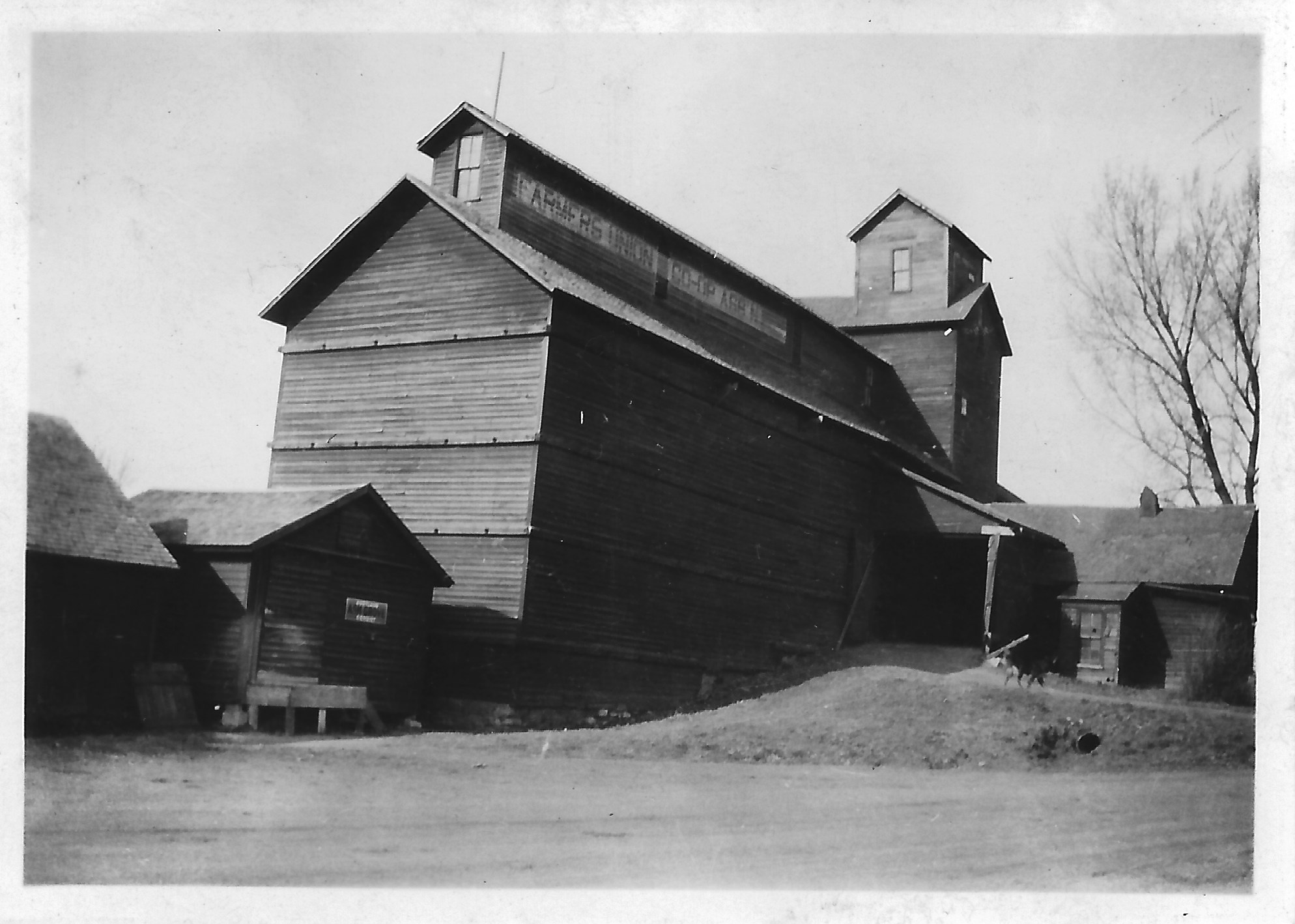
It was January of 1934, still the depths of the Great Depression, but optimism led the stockholders of Farmers Union Co-Operative Association, of Cedar Bluffs, Nebr., to decide the time had come to tear down and replace their old elevator.
Organized in 1888, Farmers Union claimed to be “the oldest cooperative elevator in the United States,” according to the New Cedar Bluffs Standard weekly newspaper. There were 200 stockholders with capital stock in the total of $50,000.
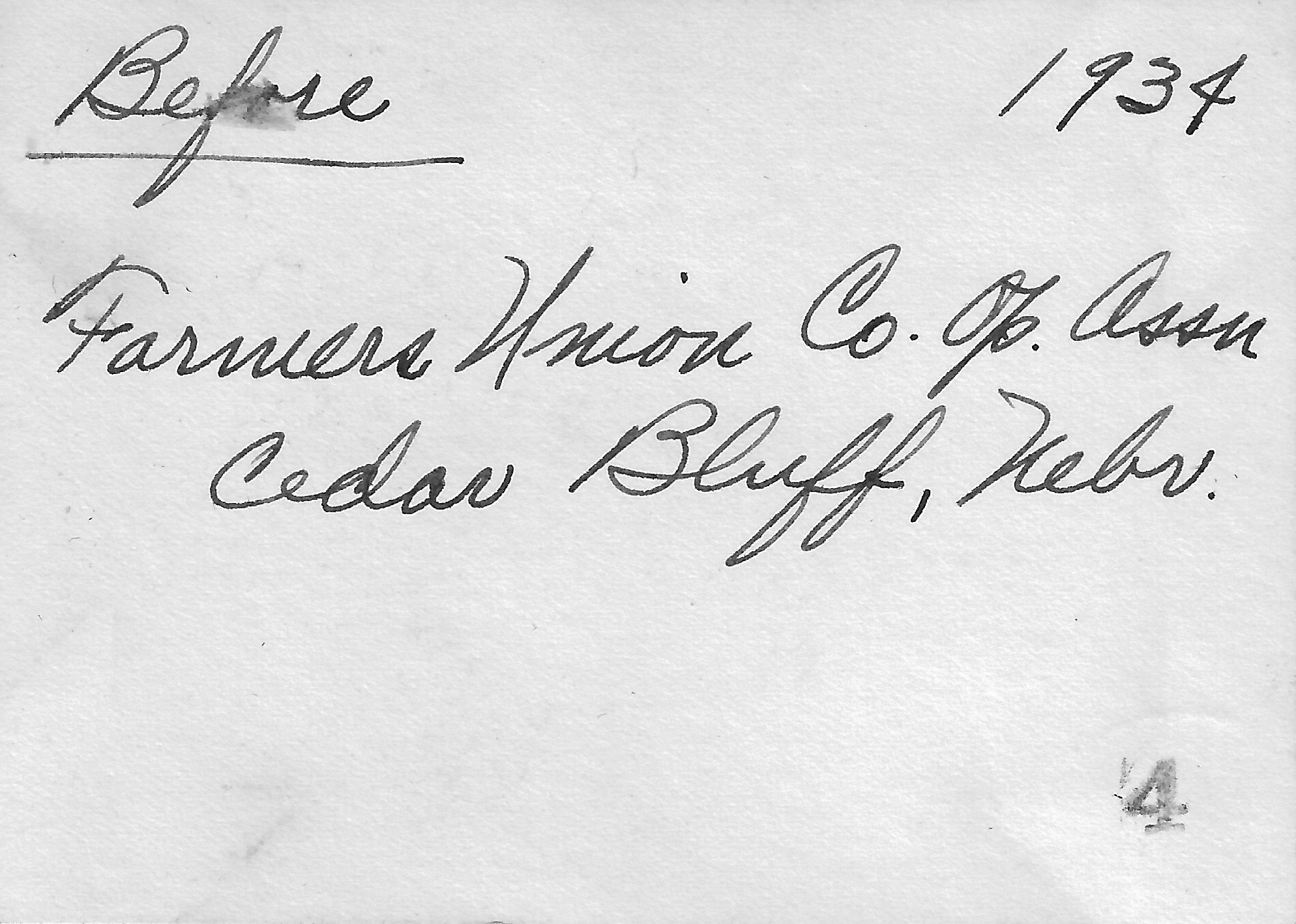
Reginald Tillotson’s neat script on the back of his photo.
At the same annual meeting, the Association announced payout of stock dividends at eight percent and patronage dividends of one percent. The newspaper remarked that “considering the times [it’s] a mighty fine showing.”
The old elevator was to be dismantled, with as much material as possible being salvaged for re-use. The new elevator would be steel-covered. The initial report stated capacity at 80,000 bushels, which is a lot for a cribbed wooden elevator. A subsequent report put it at 30,000 bushels—a more realistic figure.
The photo above shows the weathered main house with its peaked headhouse, and a storage annex with the upper structure enclosing the run being labeled Farmers Union Co-Op Assn. The shed on the left bears a sign saying Ash Grove Portland Cement.
A selling point on the rebuild was the prospect of local help getting employment in the construction.
Van Ness Construction won the job, as will be seen in a follow-up post. Tillotson Construction, which evolved from Van Ness, returned to Cedar Bluffs in 1950 to build a 130,000-bushel reinforced-concrete elevator, which we visited in 2020.
Four years after their 1937 call to remedy fire loss at George Neuswanger’s elevator in Alliance, Nebr., the Tillotsons returned to that Panhandle town with the commission to build more storage and a feed mill.
The Alliance Times-Herald reported as follows:
Construction work has begun on a large warehouse and feed processing plant here by the J.H. Tillotson contracting company of Omaha for George Neuswanger of Alliance.
We are unsure how “J.H. Tillotson contracting company” got the credit. The brothers Reginald and Joseph Tillotson formed Tillotson Construction Co. in 1938. We believe a rupture between then led to the founding of Joseph H. Tillotson, Contractor in 1948. Joe Tillotson died not long afterward in a car accident. There could be more to learn on this question, but until then we rely on existing records and previous verbal accounts.
The newspaper continued:
The building will be located just north of the Neuswanger elevator. The warehouse will be 148 feet long and 50 feet wide, and the feed processing mill will be 32 feet square. Total cost of the project has been listed at $12,000.
According to Neuswanger, some difficulty is being experienced in the obtaining of material, and he has no idea when the building which will be of reinforced concrete construction, will be completed. At this time much of the excavation work has been completed by a dragline which has been in operation this week.
The newspaper added these details:
Concrete mixing machinery is already in place at the site, a tool and supply shed has been erected, and some of the forms are being built. Much of the gravel which will be needed has been hauled to the site also.
When the feed processing plant is put into operation, mixing and grinding of many types of livestock feed will be carried on here, Neuswanger said.
In part because of the large barley crop, grain storage facilities were at a premium in those months just before the United States entered World War Two. Nebraska farmers were expected to harvest 33 million bushels of grain.
While there was sufficient capacity for 55 million bushels in total, space was available for only 13.5 million.
The federal government allowed farmers seven cents per bushel towards putting up new storage silos on their farms.
Otherwise, a state official had this suggestion: “Another way to store the coming harvest is to bind and stack it. Stacking is becoming a lost art, but it is still an excellent method.”
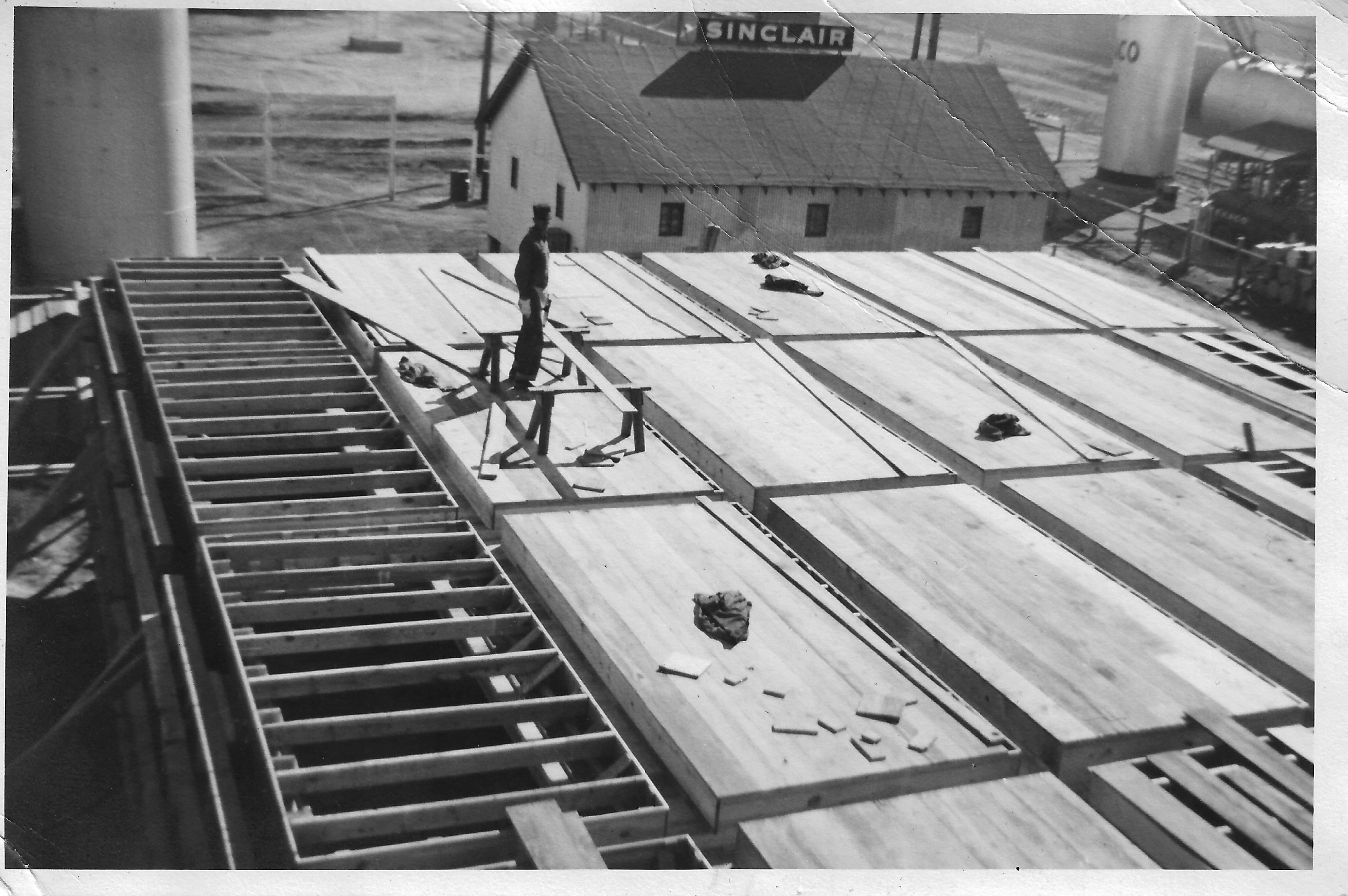
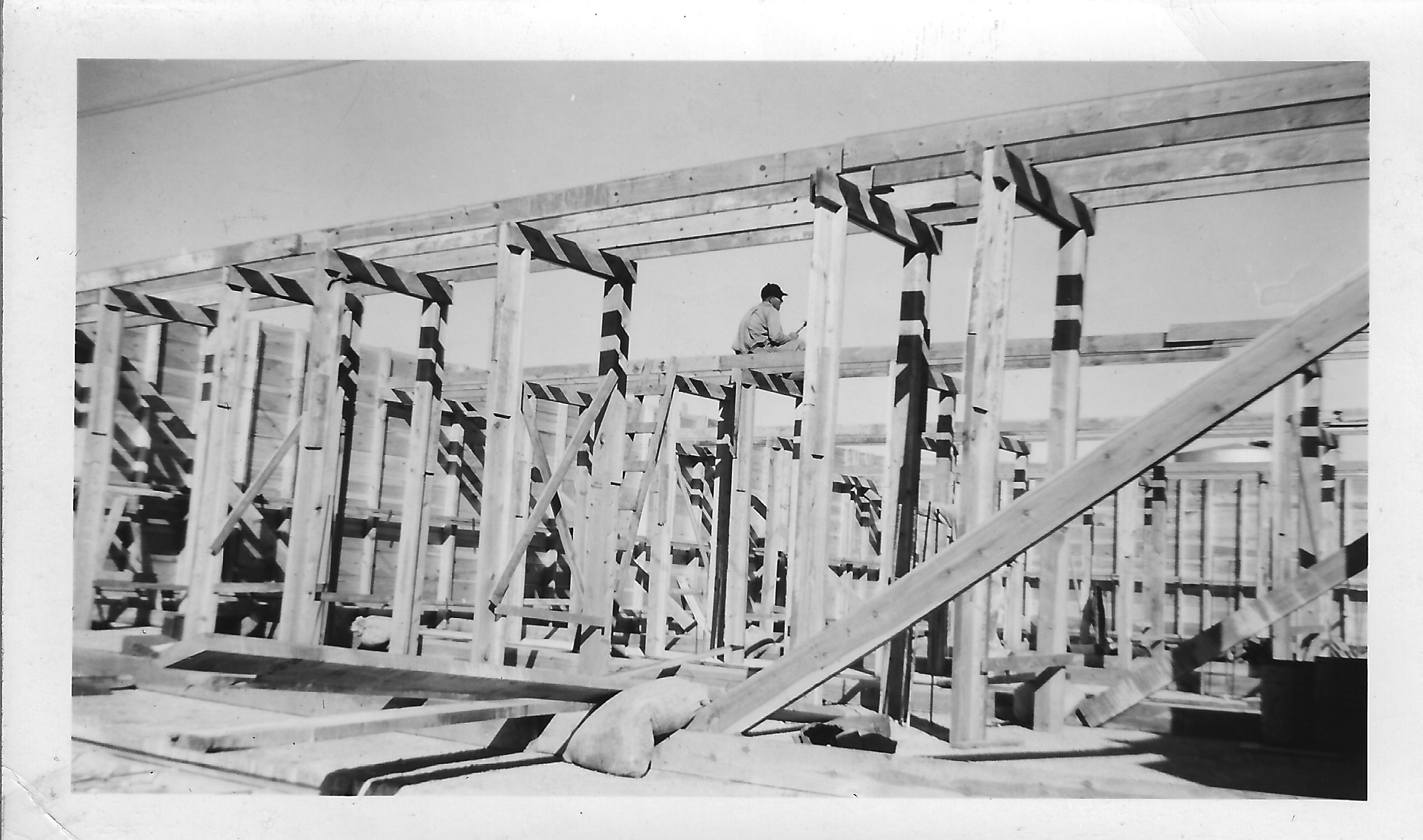
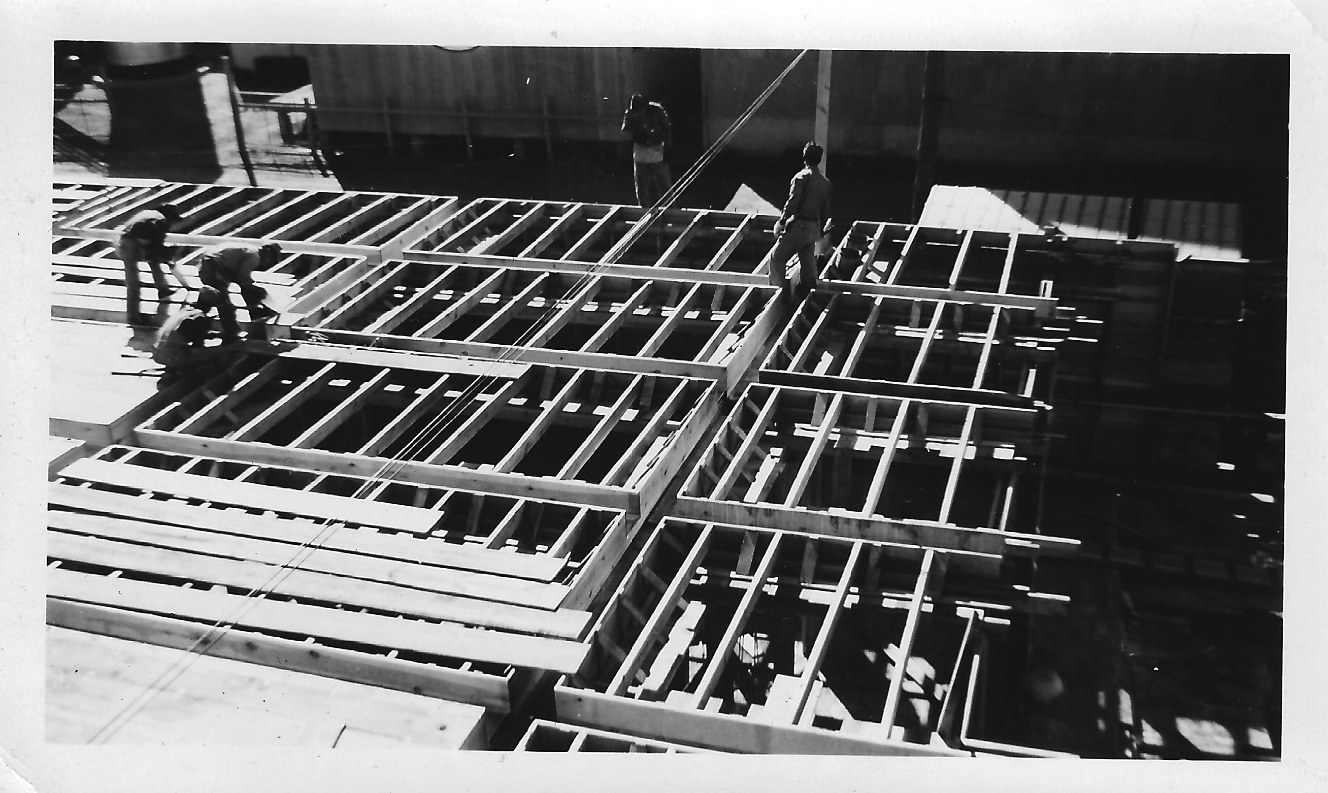
The Tillotson homestead north of Omaha was sold in 2025, and as a consequence Our Grandfathers’ Grain Elevators has received a few leaves from a photo album with snapshots of 1930s jobs. Together, these pictures comprise the earliest documentation we’ve ever seen of Van Ness Construction and Tillotson activities.
After the sudden passing of Charles H. Tillotson in 1938, his sons Reginald and Joseph built Tillotson Construction Company’s first concrete elevator, located in Goltry, Oklahoma. Prior to that, they worked for Ralston Van Ness out of Omaha. The photos we received appear to show jobs done for that company earlier in the 1930s.
Most of the photos are inscribed on the back with a name, location, and date.
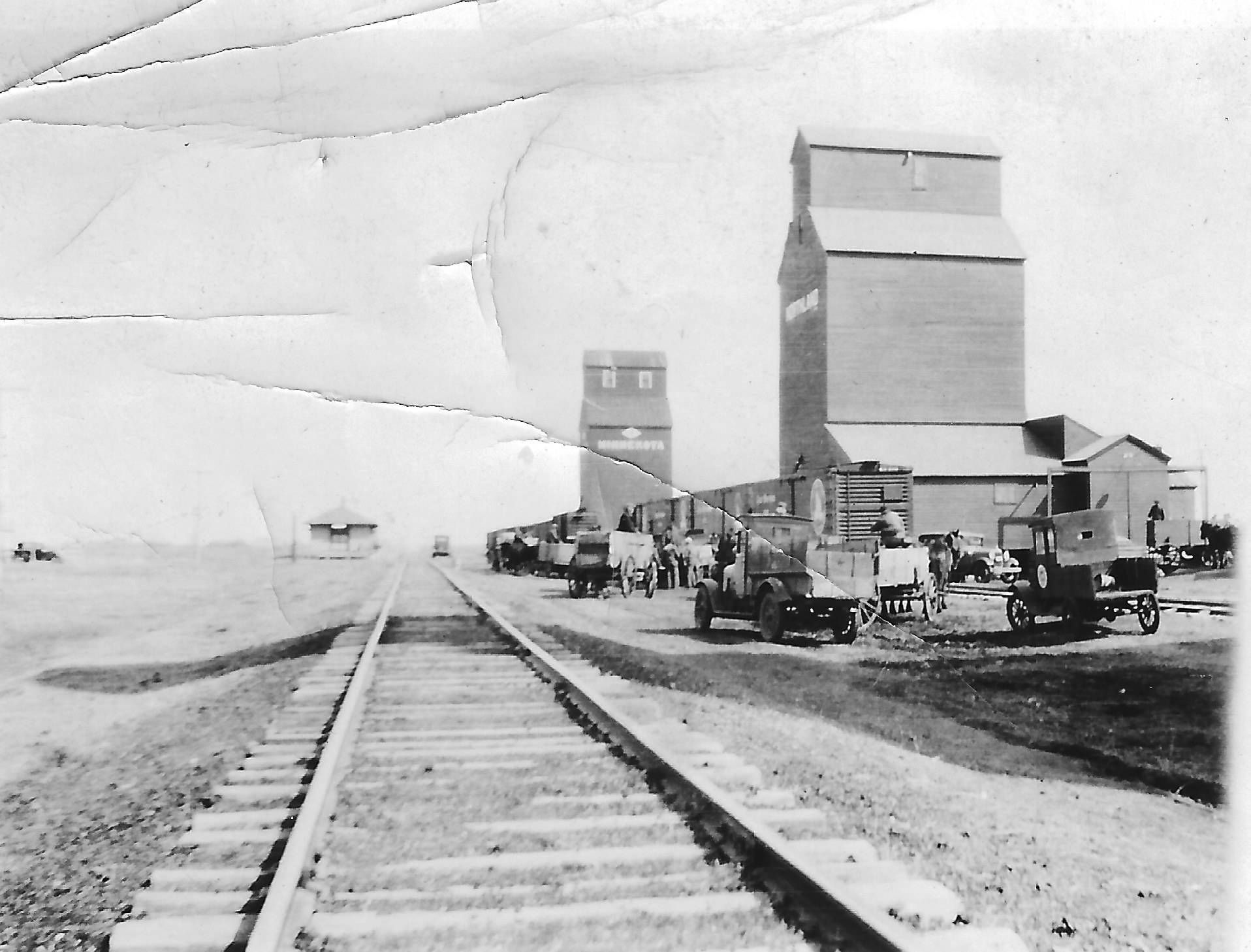
The above photo depicts a 1933 scene at a twin-elevator complex in Norma, North Dakota. Norma is a dot on the map in Renville County northwest of Minot and twenty or so miles south of the Canadian province of Saskatchewan. A note on the album page says “Rebuilt Fire Loss 1933.”
Searching through a newspaper archive turns up no more details, so we can only look at the image and suppose the relief felt by local farmers who had limited options for grain disposition. Especially at a country location like this, a damaged elevator was an unhappy circumstance that would have required hauling grain over an extended distance.
On a sunny day at Norma, a few motor vehicles converge at the complex with at least four horse-drawn farm wagons. It’s illuminating to see wagons still in use at that time. Their limitations surely gave farmers a sense of urgency about acquiring a motor truck.
An old pickup with wooden artillery-style wheels in the right foreground was likely a Ford. It has an emblem on the driver’s door, but we can’t determine anything more about it.
Under close examination of the photo, the elevator tower in the distance appears to be labeled “Minnekota.” The sign on the near tower can’t be read at all.
A number of men are going about their business, whether they’re still seated on wagon perches, standing inside a wagon, or on the ground. In the mix of trucks and cars, note the silhouette of an automobile way down the sidetrack.
Several boxcars await service. Norma is on a secondary road leading south from North Dakota Route 5, and it seems likely the rail line was a spur. This could have been part of Soo Line operations.
We lack additional information about the event that led to the reconstruction. Newspaper pages often had stories of grain elevator fires in 1932 and 1933, with casualties in Chicago at a 200,000-bushel elevator on the river there, and with lesser tolls at smaller elevators in prairie locations.
The Bismark Tribume reported on Aug. 24, 1933 that a 20,000-bushel Minnekota Grain Co. elevator had burned at Butte, North Dakota, to the southeast of Minot. It also claimed a 14,000-bushel carload of wheat. Butte was left with three elevators after the disaster.
We invite our readers to stay with us as we post the rest of the thirty photos in the newly obtained archive.
For a 2013 post, we visited the elevator at Bird City, Kan. to learn more about its provenance. Bird City (pop. 447) is in Cheyenne County, in the northwestern corner of Kansas. The county population is about 2,500.
“It has been demonstrated that the curved headhouse was a Tillotson signature,” we wrote after the site visit. “Did someone leave the Tillotson operation and branch out on his own, or were the plans sold to Vickroy-Mong?”
Later, we followed up with the story of a blowout that occurred there in 1950, not too long after the elevator was built by Vickroy-Mong Construction Co., of Salina, Kan.
Thanks to reader Steve Wilson, who grew up in St. Francis some 15 miles from Bird City, we have new views of the aftermath of that blowout, and these give a clue as to why the name Vickroy-Mong has otherwise disappeared from history.
The elevator was announced in January of 1950. The Omaha World-Herald reported as follows:
The Bird City Equity has voted to build a 250-thousand bushel storage elevator this spring. The government will assist in the finance to the extent of 80 per cent of the cost. It will also guarantee storage income for a three-year period. A drive to raise 50 thousand dollars in capital will be staged. Total cost of the elevator is estimated to be around 160 thousand dollars.
Photos courtesy of Steve Wilson
Soon after the tanks were loaded with grain, the blowout occurred. On Aug. 24, 1950, The Herndon (Kan.) Nonpareil reported:
Approximately 15,000 bushels of the 1950 Cheyenne County wheat crop spilled out on the ground about 6 a.m. Friday when a 30′ by 8′ section of the newly constructed Bird City Equity elevator caved in. The section of wall giving way was over the loading bins on the railroad. A train was in Bird City at the time and was sent to St Francis to be turned after wheat augers brought in from the surrounding countryside had cleared a path through the grain on the tracks. More than six boxcars of wheat were loaded with the augers after the engine returned, but between 6,000 and 7,000 bushels of wheat still remained on the ground the next day, A.A. Gillispie veteran St. Francis newspaperman reported. The elevator which has a capacity of 250,000 bushels was finished shortly before harvest this year.
Photos by Gary Rich
Chalmers & Borton received the contract for the repair work. In 1958, they also won the contract for an addition of 241,000 bushels.
W. Stephen “Steve” Wilson retired as professor of mathematics at Johns Hopkins University and lives in Baltimore. His father, Charles Wm. Wilson, M.D., served the people of Cheyenne County “doing everything from glasses to babies to surgery.” And Dr. Wilson was a photography buff. Steve Wilson provides this addendum regarding the blowout:
I was only 4, or almost 4, but it was a big deal. Lots of grain elevators in that part of the country, and they don’t usually fall apart. Worth the drive to see it!
In 2009, I took my kid out to see where I was from (the year before he graduated from high school). We went out to one of the elevators in St. Francis, the county seat. This was an elevator [where] they would take us kids up to the top, and we would throw model airplanes with cherry bombs in them.
However, when my son and I started walking towards the elevator, someone ran out of the office and told us we couldn’t get close to the elevator. Homeland security rules. What a waste of resources! If a terrorist wants to blow up a grain elevator in a town of 1,500 where you still have to drive 175 miles to get to a town of 25,000, that’s not a bright idea. Spending money to prevent it is even stupider.
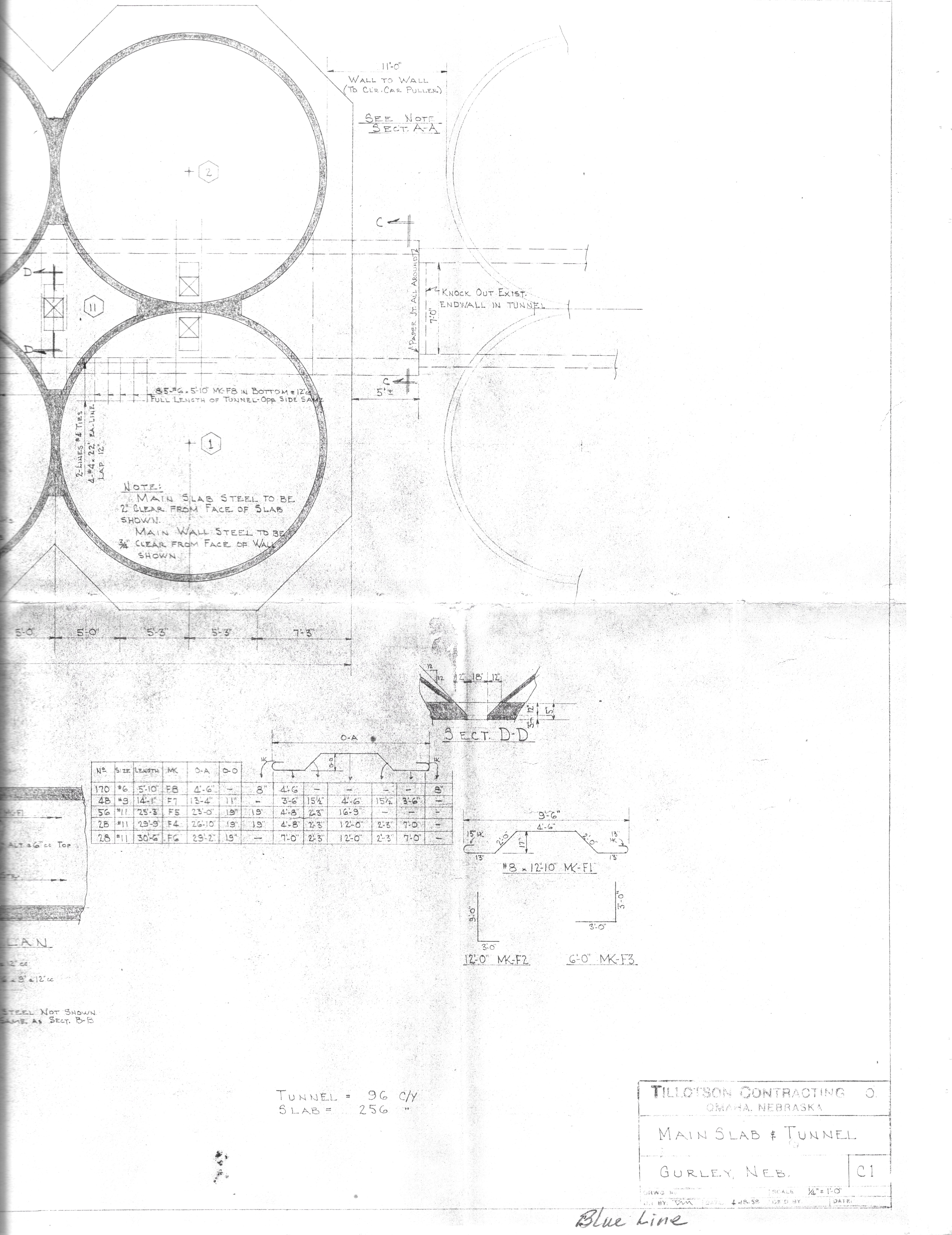
Finally, mercifully, we get to the last of the drawings from Tillotson Construction Co. records, and instead of dark, hard-to-read copies of blueprints, we offer these scanned copies of a “blue line.” They’re for a main slab and tunnel at Gurley, Neb.–which we assume has something to do with an annex–and were completed by Ted Morris on April 18, 1958. The scale is indicated as one-quarter-inch to one foot.
These are among the most detailed drawings in our possession, with abundant dimensional markings and figures for steel reinforcing bars. There are also many notations, some comprehensible and others begging for clarifying comments. In the upper right, the note, “Knock out Exist. Endwall in Tunnel” seems to suggest a conveyor that would connect the annex to the elevator.
Above that, an 11.0-foot gap is indicated between slabs with the note, “Wall to Wall (to Clr. Car Puller). Hmm!
Another one, between the Number Six and Number Four tanks, says, “Truss Bars next to Tank Opg’s. Str. Bars next to Inner Opgs.”
And in Number One we read, “Main Slab Steel to be 2″ Clear from Face of Slab Shown. Main Wall Steel to be 3/4″ clear from Face of Wall Shown.”
Others are far trickier. For example, “Print Walls for Roof” is written in Number Eight, and that’s pretty obscure.
Gurley is located in the Nebraska panhandle a few miles north of Sidney and Interstate 80. A satellite view reveals the annex and main elevator quite clearly amid Crossroad Coop’s complex at 501 Lincoln St. and ought to satisfy reader Suzassippi’s desire to match the two-dimensional drawing with a photographic view.
Readers may please feel free to contribute their own interpretations via the comments feature.
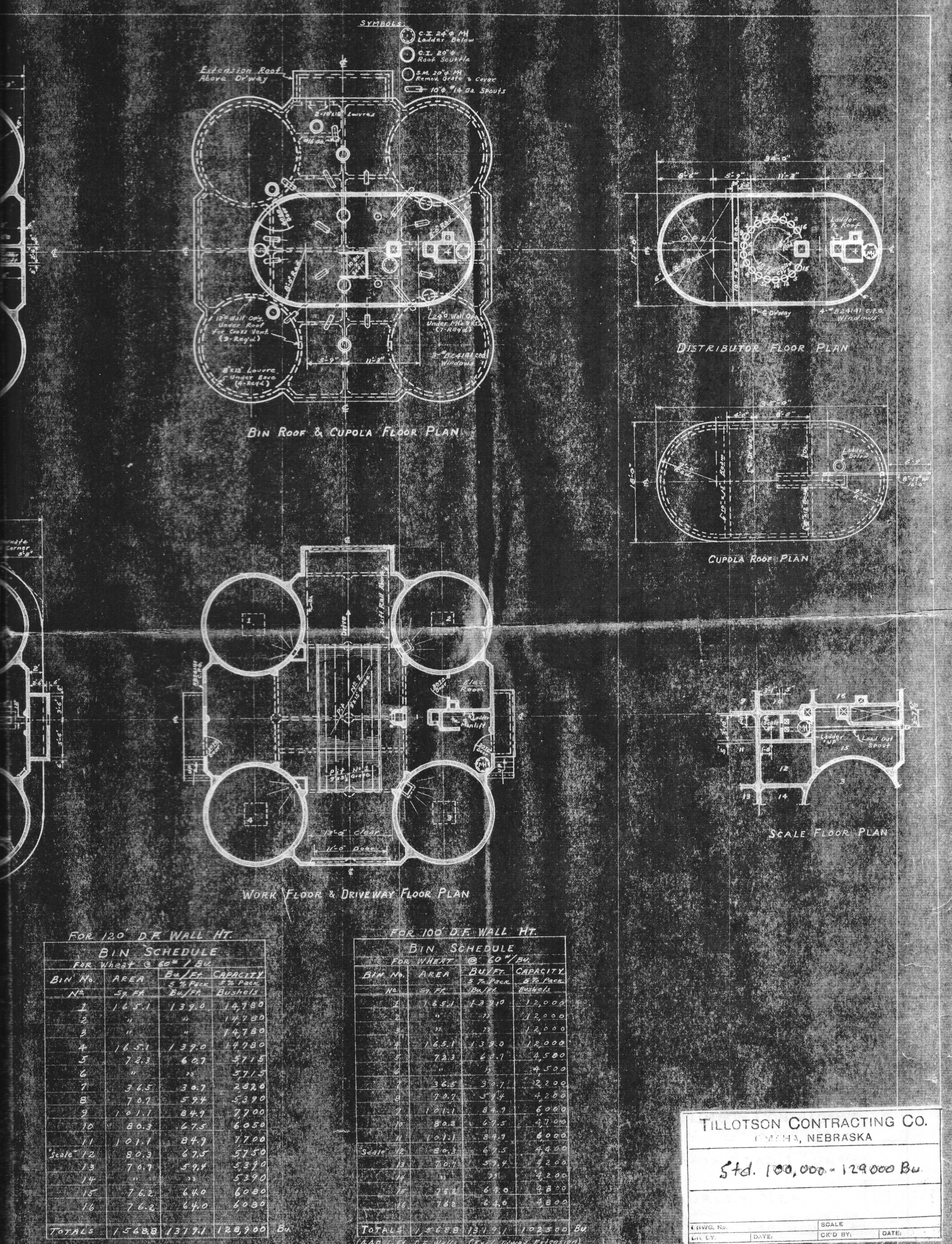
Among the most detailed drawings in our possession is this print, from the records of Tillotson Construction Co., of Omaha, for a 100,000- to 129,000-bushel, single-leg reinforced-concrete grain elevator.
We assume that Ted Morris executed the drawings for the company. We do not see notations for the scale of these drawings in inches to feet, as in others previously posted. Otherwise, the drawings are meticulously rendered.
To the left above is the cross-section of the structure. The main house has four tanks (silos) with internal diameter of 14 feet six inches and, with 100-foot drawform walls, a 102,500-bushel capacity is achieved. At 120 feet, the capacity increases to 128,900 bushels.
The cupola is marked as 22.0 feet high and 34.0 feet wide. Special markings indicate the dimensions of segments within and atop the cupola. A notation at the roof indicates the centerline of the driveway far below. We also see inscriptions for the head pulley, top of manlift travel, an interior ladder nearby, and to the far left, a 10-inch-diameter, 14-gauge spout.
In the main house, bins are numbered. From left to right, we see internal Bins 5, 11, 12, and 15.
Above the driveway and work floor, a space that extends 17.0 feet accommodates the 12.0-foot steel overhead-curtain-type door and electric truck-lift rails. The grate is 9.0-feet wide. The pit goes 12.0 feet below the main slab. A note indicates “Typ. Base Sash Elev.,” the meaning of which is open to interpretation although it obviously refers to a window. An entry in the Standard Machinery list includes, “Industrial steel windows & Doors @ Cupola & Work Floor.”
Below the cross-section is a Boot Pit Plan showing two pits and a ladder up, with dimensions given.
The Bin and Foundation plans give the various specifications and dimensions, including a 44.0 x 44.0 slab and 9 foot 9-inch radius from center of a tank to the outside perimeter.
The Bin Roof & Cupola Floor Plan includes such juicy details as the dimensions of wall openings under the roof and louvres under eaves and indicates three “B24141 cpd” windows. A key to symbols explains markings for “C.I. 24-inch manhole [with] ladder below,” “C.I. 20-inch roof scuttle,” “S.M. 20-inch removable grate and cover,” and 10-inch 14-gauge spouts. The scale is rated for 10 bushels.
The Work Floor and Driveway Floor Plan shows the driveway curtain door is 11.0 feet wide and opens to an area with 13.0 feet of clearance. The two dump grates are indicated. No. 1 is 9.0 x 3.5 feet )or it could be 5.5 feet), and No. 2 is 9 x 15 feet. Doors are 3070 doors.
The Distributor Floor Plan depicts 18 funnels at 16-inch centers, and a radius of 4 feet 7 inches from center. There are four of the B24141 C.P.O. windows.
The Scale Floor Plan shows the scale, a ladder up, and the load-out spout, as well as various dimensions.
The list of Standard Machinery includes the following:
Head & Boot Pulley 60 x 14-inch C.I.
Belt 14-inch, six-ply
Cups 12 x 6-inch Calumet at 9-inch centers
Leg capacity 5,000 bushels/hour
Head drive 25 or 30 H.P.
Truck Lift 7 1/2 H.P. Elec.
Manlift 2 H.P. Elec.
Dust col. System 3 H.P. Fan @ Head, Disch[arge] to Bin
Leading Out Scale 10 Bu. Richardson
Leading Out Spout 8 1/4-inch well casing
Cupola Spouting 10-inch-diameter, 14-gauge steel
Car Unloading Facilities By Gravity, Direct to Boot
These drawings reproduced from the records of Tillotson Construction Co., of Omaha, show the general-plan details of a 100,000- to 125,000-bushel, single- or twin-leg, reinforced-concrete elevator.
To the left above, seen at the scale of one-eighth inch to one foot, is the cross-section of the structure. The main house has four tanks (silos) with internal diameter of 14 feet six inches and, at 100 feet in height, a 100,000-bushel capacity is achieved. At 120 feet, the capacity would increase to 130,000 bushels.
The cupola is marked as 22.0 feet high with a single leg and 30 feet 6 inches with two legs. Notations inscribed in the cupola space label the dust fan, distributor floor, automated scale, and cupola floor. The diameter of the leg’s head pulley is 60 inches.
In the main house, bins are numbered. From left to right, we see Bin 5, Bin 11, Bin 12, and Bin 15.
Above the driveway and work floor, a space that extends 17.0 feet accommodates the steel overhead-curtain-type door and electric truck-lift rails. The main slab is indicated below.
At the very bottom, we see a 13 foot 6 inch depth for the pit with a single leg or 15 foot 9 inch depth for a twin-leg setup.
The driveway floor plan (center) is rendered at the scale of one-quarter inch to one foot. To the far left, we see a dock. The measure of 13.0 feet is given between the two tanks (Numbers 1 and 4). The driveway is 47.0 feet long–three feet longer than the main slab. It is 30.0 feet from the initial edge of the second dump grate to the driveway exit. The width is 13.0 feet. On the right are the electrical room, an electrically operated manlift, and a manhole.
The variation drawing, “Dvwy Floor Plan 2 Legs,” at the same quarter-inch scale, includes details for a twin-leg elevator. The note at bottom says, “Remainder of Plan same as with 1-leg.”
The Bin Plan at the right shows a 44.0-foot width. (So the main slab is apparently 44.0 x 44.0 feet.) At top we see a dust bin noted as well as bin draw-offs in the interior bins. A number of those bins are marked as 10 feet 4.5 inches across. Number 12 is 7 feet 11 inches wide. Number 16 is 12 feet 10 inches.
At lower right, the twin-leg variation drawing shows the distribution-control cable well–not indicated in other drawings we’ve posted–and the manlift and ladder well and manlift weight box.
The large tanks Numbers 1 to 4 are shown in counter-clockwise order from the upper right. At 100,000-bushels overall elevator capacity, Numbers 1 and 4 hold 11,996 bushels. Numbers 2 and 3 hold 12,066 bushels. At 125,000-bushel capacity, Numbers 1 and 4 hold 14,770 bushels. Numbers 2 and 3 hold 14,840 bushels.
The internal bins are at 100,000/125,000-bushel ratings as follows for single and twin-leg configurations:
Bins 5 & 6: 4,555/5,7770 bushels
Bins 7: 2,207/2,400 bushels
Bin 8, 13, 14: 4,217/5,400 bushels
Bin 9 & 11: 6,030/7,730 bushels
Bin 10: 4,790/6,140 bushels
Bin 12 (scale): 4,452-4,014 (1-2 leg)/5,800-5,460 (1-2 leg) bushels
Bin 15: 4,858 (1-2 leg)/6,150 (1-2 leg) bushels
Bin 16: 4,790-4,465 (1-2 leg)/6,070-5,655 (1-2 leg) bushels
These drawings reproduced from the records of Tillotson Construction Co., of Omaha, show the general-plan details of a 150,000-bushel, single-leg, reinforced-concrete elevator.
To the left above, seen at the scale of one-quarter inch to one foot, is the cross-section of the structure. The main house has five tanks (silos) with internal diameter of 16.0 feet and achieves a height of 120 feet. No dimensions are shown for the cupola; the only notation in the plan says “automatic scale.”
In the main house are notes saying, “Up Leg” and “Down Leg. Other say, “Elect. Truck Lift” and “Dump Grate.” The driveway door is 13.0 feet high.
A precisely rendered rail car provides a fanciful touch on the far right, where it’s positioned at the load-out spout to receive a cargo.
At the very bottom, we see a 21.0-foot depth below the main slab.
The work floor plan (center) is rendered at the scale of three-sixteenths inch to one foot. We see that the whole structure sits on the slab measuring 50.0 x 47.0 feet. Internal diameter of the tanks is 16.0 feet. Notes show the locations of the electrical room, two manholes, dump grates, and at far right the dock.
The bin plan, also three-sixteenths to one foot, shows the five large tanks with Number 1 in the lower-right and the progression going counter-clockwise to Number 5 on the lower-left.
Sandwiched inside are Bins 6 through 16. We see that Bins 6, 8, 10 and 12-16 are marked as being 10.0 feet wide. Bin 9 is 7 feet 6 inches across. Bin 14, on the far right, is 13 feet 9 inches across. Bin 16 is labeled “Dust Bin.”
The large tanks Numbers 1 to 5 have capacities of 17,650 bushels. The internal bins are as follows:
Bins 6-7: 5,300 bushels
Bins 8 & 10: 6,790 bushels
Bin 9: 6,000 bushels
Bin 11: 6,540 bushels
Bin 12: 2,640 bushels
Bin 13: 5,300 bushels
Bin 14: 8,220 bushels
Bin 15: 7,980 bushels
Bin 16 (Dust Bin): 930 bushels
Unlike any of the other plans we have, this one is dated. One entry in the lower-right says, “Rec’d 3-3-58.” There are two other illegible dates, but at very bottom another date shows 3/31/58.
The initials “TM” would seem to indicate that Tillotson’s Ted Morris executed the drawings.
The present drawings that are reproduced from records of the Tillotson Construction Co., of Omaha, show details of a 200,000-bushel, single-leg, reinforced-concrete elevator
To the left above, seen at the scale of one-eighth inch to one foot, is the cross-section of the structure. The main house has eight tanks (silos) with internal diameter of 15 feet six inches and achieves a height of 120 feet. The cupola is 30 feet six inches high. At the bottom, we see a depth of 15 feet three inches below the main slab.
In the cupola, we see notations for the distributor, distribution floor, and automatic scale.
Below, numbers of the large tanks and smaller interior bins are noted. The driveway and rolling door are shown above dump pits Number One and Two. The driveway is 12 feet wide, the door is 13 feet high, and a 17-foot distance extends between driveway floor and driveway roof.
Other notes in the lower-right indicate the work floor, back pit, and a track conveyor to be installed at a future time.
Outside the elevator’s wall is a load-out spout for rail cars and the inscription “Track,” showing where a car draw up to be filled.
Ratings for the bin schedule are cut off due to the limitations of our scanner bed and the 11×17-inch sheets that were copied from blueprints by Uncle Tim Tillotson.
The schedule has the large tanks, Number One through Seven, at 16,880 bushels each. Number Eight is 15,495 bushels. Internal bins nine through 20 range in capacity from 3,980 bushels (Number 19) to 6,665 bushels (12 and 14).
The whole structure sits on the slab measuring 48.5 x 62.0 feet.
Number 21, which can barely be seen in the Bin Plan, is an ovalized chute that stands just outside the accommodations for the electrically operated man lift. “Down” is inscribed to the left of the lift, and “loader” and “up” are to the right.
The Bin Plan and Work Floor Plan are shown at the scale of three-sixteenths inch to one foot.
From the bottom, notes in the Work Floor plan show “Trucks” entering in the direction of the arrow to the two dump pits. Additional notes say “Rails for the 7 1/2 H.P. overhead Electr. Truck Lift” and “12′ wide x 13′ high Overhead Steel Curtain Type Door (Opp. end same).”
At far right, notes say “Track Door” and “RR Siding.”
The stairway inside Number Eight is indicated with the note “Down to Bsm’t.” And this stairway is the reason for the tank’s capacity of 15,495 bushels as opposed to the 16,880 bushels of the others.
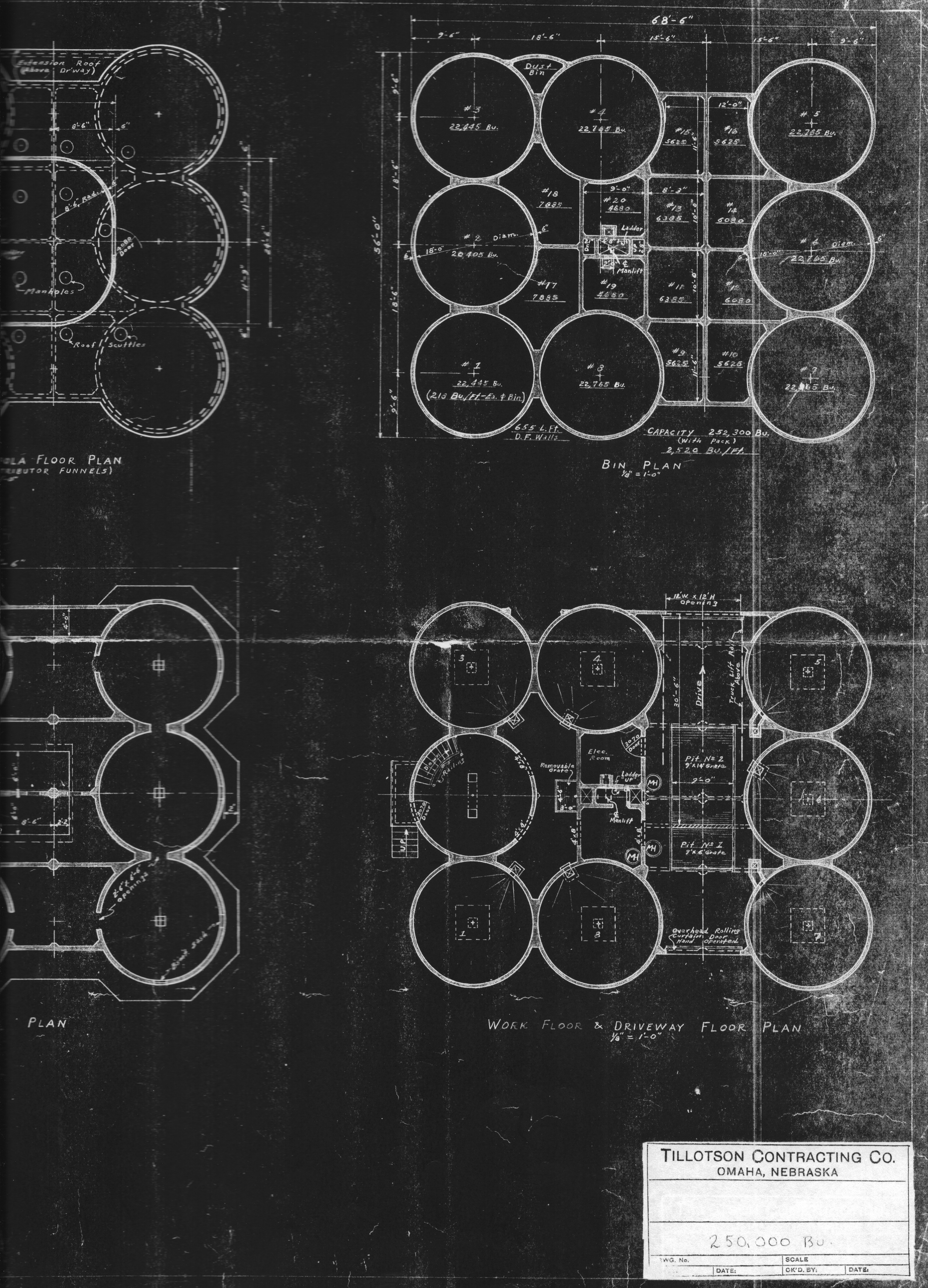
Here in sharp detail, at the scale of one-eighth-inch to one foot, we have drawings for a 250,000-bushel Tillotson elevator. The bin plan gives capacity at 252,300. Tillotson Construction Co. built many elevators of this capacity, although we can’t determine how many of them adhered to the drawings we see here.
The level of detail is exceptional. In the cross-section, we see a stairway and its railing, an interior ladder (apparently in the manlift channel), basement window sash, 7.5-horsepower Ehrsam truck lift and hand-operated rolling curtain door, port for inspection of the leg, and the 72×14-inch head and boot pulleys. A note on the lower left says “Future 3 hp – 14″ conveyor,” and broken lines indicate its course. Another note to the left indicates “10[-inch] well casing”. Another note near the top of this channel says, “Rad. Dist. to 3 bins & Loading Spout & Driveway.” This we take to mean radial distribution.
The “car” at far left presumably represents a rail car.
The drawform walls of the tanks (silos) are 120 feet high.
The cupola is 40 feet high and 50 feet 3 inches long. We learn that inside it, a 40-horsepower Howell head-drive turns the head pulley at 42 revolutions per minute. The leg’s 14-inch, six-ply belt has cups of 12×6 inches for a leg capacity of 6,300 bushels per hour.
Another note and a zig-zag arrow indicate “Top of Manlift Travel” and two-horsepower Ehrsam manlift.
Detail drawings inside the cupola show the intake and exhaust for the three-horse exhaust fan. Made of 14-gauge steel, the spouting is 10 inches in diameter. Another notation and additional broken lines indicate “Future 2,500 bu. Hopper Scale.” This is near the automatic scale and the grate platform.
Other plans–each with its own details–are for the roof and the cupola floor, bins, foundation, and work floor and driveway.