
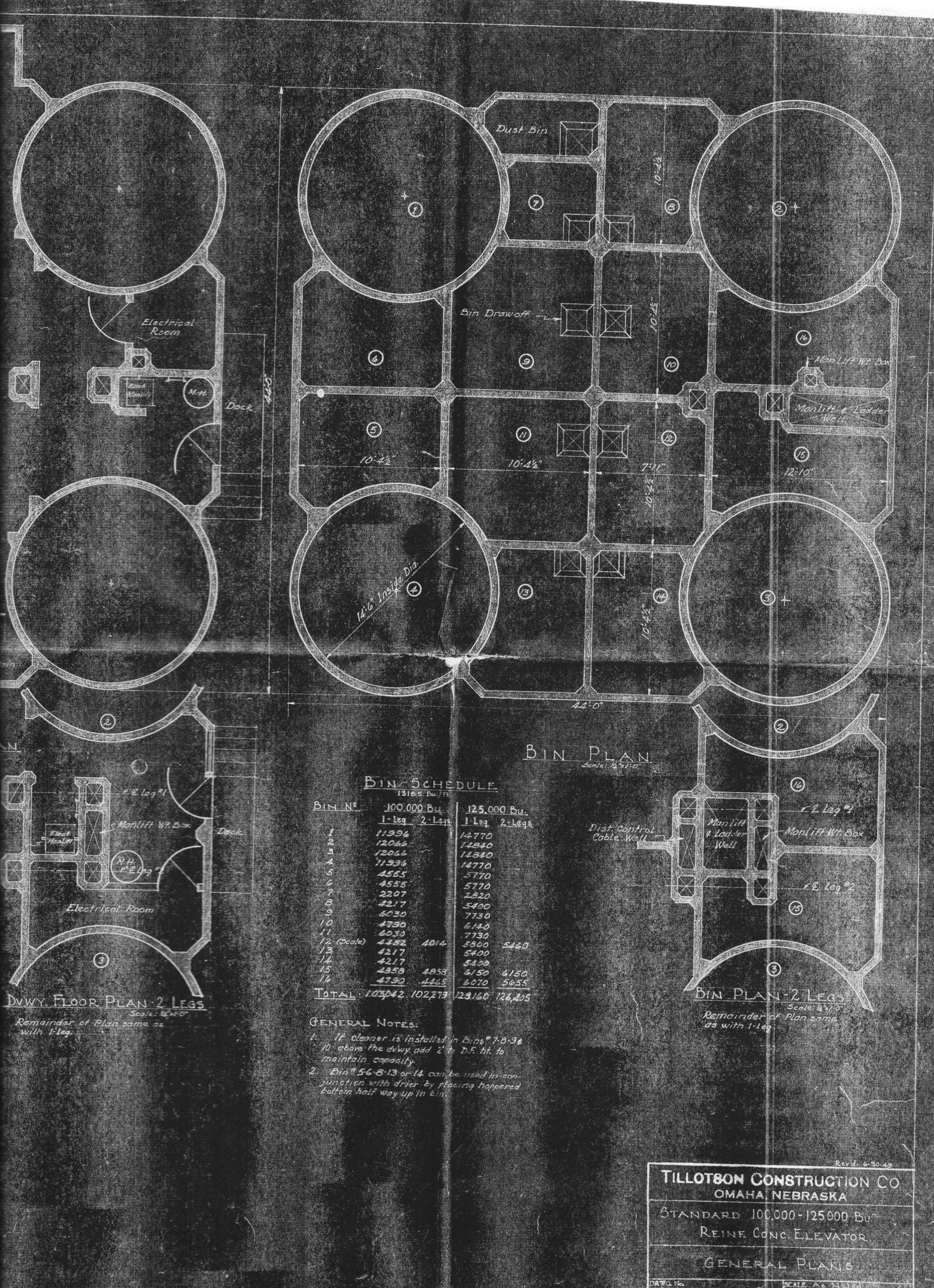
These drawings reproduced from the records of Tillotson Construction Co., of Omaha, show the general-plan details of a 100,000- to 125,000-bushel, single- or twin-leg, reinforced-concrete elevator.
To the left above, seen at the scale of one-eighth inch to one foot, is the cross-section of the structure. The main house has four tanks (silos) with internal diameter of 14 feet six inches and, at 100 feet in height, a 100,000-bushel capacity is achieved. At 120 feet, the capacity would increase to 130,000 bushels.
The cupola is marked as 22.0 feet high with a single leg and 30 feet 6 inches with two legs. Notations inscribed in the cupola space label the dust fan, distributor floor, automated scale, and cupola floor. The diameter of the leg’s head pulley is 60 inches.
In the main house, bins are numbered. From left to right, we see Bin 5, Bin 11, Bin 12, and Bin 15.
Above the driveway and work floor, a space that extends 17.0 feet accommodates the steel overhead-curtain-type door and electric truck-lift rails. The main slab is indicated below.
At the very bottom, we see a 13 foot 6 inch depth for the pit with a single leg or 15 foot 9 inch depth for a twin-leg setup.
The driveway floor plan (center) is rendered at the scale of one-quarter inch to one foot. To the far left, we see a dock. The measure of 13.0 feet is given between the two tanks (Numbers 1 and 4). The driveway is 47.0 feet long–three feet longer than the main slab. It is 30.0 feet from the initial edge of the second dump grate to the driveway exit. The width is 13.0 feet. On the right are the electrical room, an electrically operated manlift, and a manhole.
The variation drawing, “Dvwy Floor Plan 2 Legs,” at the same quarter-inch scale, includes details for a twin-leg elevator. The note at bottom says, “Remainder of Plan same as with 1-leg.”
The Bin Plan at the right shows a 44.0-foot width. (So the main slab is apparently 44.0 x 44.0 feet.) At top we see a dust bin noted as well as bin draw-offs in the interior bins. A number of those bins are marked as 10 feet 4.5 inches across. Number 12 is 7 feet 11 inches wide. Number 16 is 12 feet 10 inches.
At lower right, the twin-leg variation drawing shows the distribution-control cable well–not indicated in other drawings we’ve posted–and the manlift and ladder well and manlift weight box.
The large tanks Numbers 1 to 4 are shown in counter-clockwise order from the upper right. At 100,000-bushels overall elevator capacity, Numbers 1 and 4 hold 11,996 bushels. Numbers 2 and 3 hold 12,066 bushels. At 125,000-bushel capacity, Numbers 1 and 4 hold 14,770 bushels. Numbers 2 and 3 hold 14,840 bushels.
The internal bins are at 100,000/125,000-bushel ratings as follows for single and twin-leg configurations:
- Bins 5 & 6: 4,555/5,7770 bushels
- Bins 7: 2,207/2,400 bushels
- Bin 8, 13, 14: 4,217/5,400 bushels
- Bin 9 & 11: 6,030/7,730 bushels
- Bin 10: 4,790/6,140 bushels
- Bin 12 (scale): 4,452-4,014 (1-2 leg)/5,800-5,460 (1-2 leg) bushels
- Bin 15: 4,858 (1-2 leg)/6,150 (1-2 leg) bushels
- Bin 16: 4,790-4,465 (1-2 leg)/6,070-5,655 (1-2 leg) bushels
- Total: 103,042-102,279 (1-2 leg)/128,160-126,405 (1-2 leg) bushels
General Notes:
- If cleaner is installed in Bins #7-8-9 & 10 above the dv’y, add 2′ to D.F. [drawform] ht. to maintain capacity.
- Bin 5-6-8-13 or 14 can be used in conjunction with drier by placing hopper bottom half way up in bin.
The initials “TWM” in “DR BY:” box at bottom right indicate that Tillotson’s Ted Morris executed the drawings.
