Our Grandfathers’ Grain Elevators marked its 10th anniversary four months ago, but in the crush of the holiday season and early 2022 resort activities in Palm Springs, which is one location of our split headquarters, we forgot to mention it until now.
Thank you to all followers of our blog.
In these 10 years, our 455 posts have attracted 72,271 visitors and 158,294 page views. Just today, we’ve had looks from China, Portugal, Lithuania, Canada, and the Netherlands in addition to the United States.
Also in these 10 years, it can be said that we–Kristen Osborn Cart and Ronald Ahrens–have become excellent friends. You see us pictured above in May of 2021, when Kristen was able to parachute into Palm Springs and accompany me to the track, where I did an assignment for Robb Report. Then we went to the south shore of the Salton Sea and took pictures of burrowing owls.
Through our posts, we’ve made friends with readers, too.
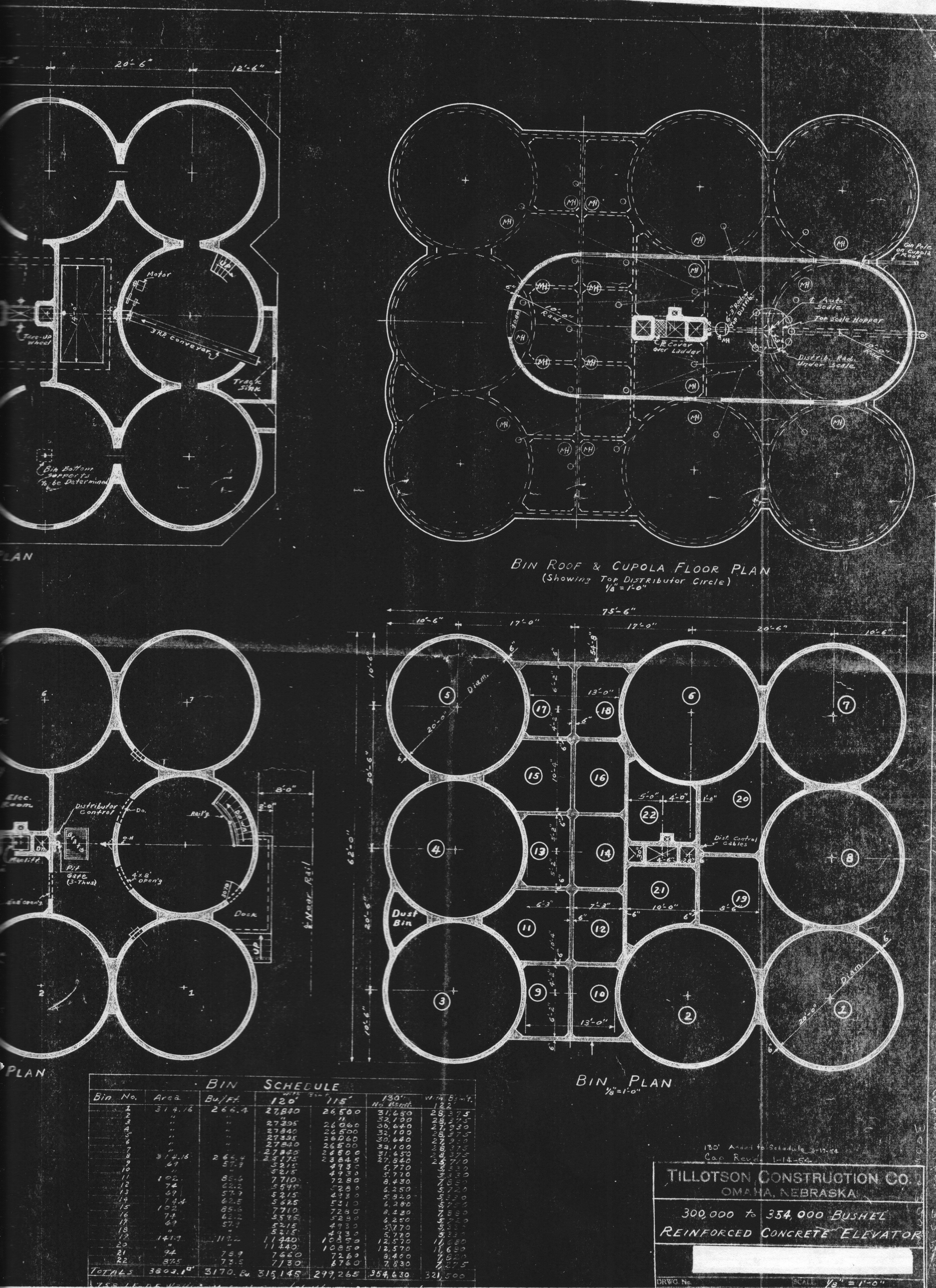
Our favorite moments in this pursuit are personal visits to our grandfather’s elevators, but we also have been lucky in getting our hands on construction records. Not long after we got going on this project, Uncles Tim and Chuck Tillotson put their heads together and came up with valuable documents.
We also love it when comments come in or readers extend their personal stories, photos, and art–all of which have been important to our effort.
On this anniversary, we would like to share a bit more from our personal perspectives.
10-Year Journey, by Kristen Cart
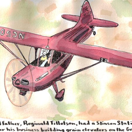
The blog started very much by chance. I wanted to find the elevators my grandfather, Bill Osborn, built. My dad, Jerry Osborn, knew the locations for the projects and the names of grandpa’s boss, Reginald Tillotson, and his superintendents, so I began to scour the internet to find them. That is how I found Ronald Ahrens. In 2009, he had written a post on his personal blog about his grandfather, Reginald Tillotson, and his airplane, which was pressed into service for elevator stuff. I wrote a comment on the blog. So began a very productive relationship.
Early on, we partnered with a photographer and elevator enthusiast named Gary Rich. He was a retired Union Pacific man, and he has since passed away. He traveled around many of the places where our grandfathers plied their trade, and he accumulated a formidable collection of elevator images. He gave us views of elevators that are now demolished—some of which we never had a chance to see. I had occasion to do an elevator tour and photo shoot with him. He would look at my images and tease me about removing the rock in my shoe—almost all of my pictures tilted to one side or the other. He was a very good photographer and critic.
Gary is not the only contributor who has passed on to greener pastures. Many of the men who did the work in the 1940s and 1950s were older than our World War Two veterans, and most of them are gone. The interviews and photos in this blog gave voice to some of these men and women.

I look through our past posts and see a few that were started and not quite finished—I confess to being the guilty party. Usually some scrap of information was misplaced or missing. If I never got back to it, mea culpa. Palmer, Iowa, was one such post—I still have hopes of finishing it.
I don’t get around to a lot of the places as much anymore. I’m not the stalwart road-tripper I once was. But I will never forget how Ronald taught me about taking strong photos with context, and about interviews that bring people to life in print.
The blog has been a great ride. Here’s to another ten years.
Figuring out the Hidden Meanings, by Ronald Ahrens
When Kristen tracked me down in 2011, I had just moved to Southern California after 25 years in Michigan, and the last thing on my mind was grain elevators. During my youth in Omaha, Neb., everybody in the family knew that our maternal grandfather, Reginald O. Tillotson, had built grain elevators. But we knew nothing beyond that.
Kristen got the ball rolling. Genealogy was her established interest, and she had come up with some news clips that served as kindling for the great conflagration that’s followed.

It’s hard for me to get to many elevator sites–the nearest one of “ours” is in Tempe, Ariz.–and besides that I keep busy as a freelance writer. But as mentioned, we came into the possession of more records, and by hook and crook, we’ve also managed to visit elevators in Texas, Oklahoma, Colorado, Nebraska, and Iowa.
My other big challenge has been learning how an elevator works. It certainly can be said that my inventory of lingo has increased. What other buildings come with such a rich lexicon? Boot, manlift, main house, cupola/headhouse, and load-out spout are a few examples.
In my career, I’ve written for 80 magazines and 24 newspapers, including some you’ve heard of. (For example, my byline and in some cases my own photos have appeared in The Wall Street Journal, The New York Times, New York Post, and USA Today.) But I can say with satisfaction that Our Grandfathers’ Grain Elevators is equally significant, and part of the pleasure is in doing it our way.
Here’s to the next site visit!