 Story and photos by Kristen Cart

The Boxholm elevator located in central Iowa was an intriguing destination, particularly since I had knowingly passed it by, missing it by a few miles on more than one trip. It became imperative to make the detour to see it. I was glad I did, since the elevator made beautiful pictures on that early summer day. I used a wide-angle lens that added pronounced distortion to the scene, causing the buildings on the edges to lean in dramatically. But the leaning lines pointed to the beautifully clouded sky.
You can use a wide-angle lens to include more of the scene from close quarters than would be possible with another lens, but you forfeit realism. This is not a problem for certain artistic photos, but it is not ideal for documentary shots. When photographing buildings where you want to preserve parallel lines, you must stand farther away and use a longer focal-length lens. At Boxholm, I did not have that option.
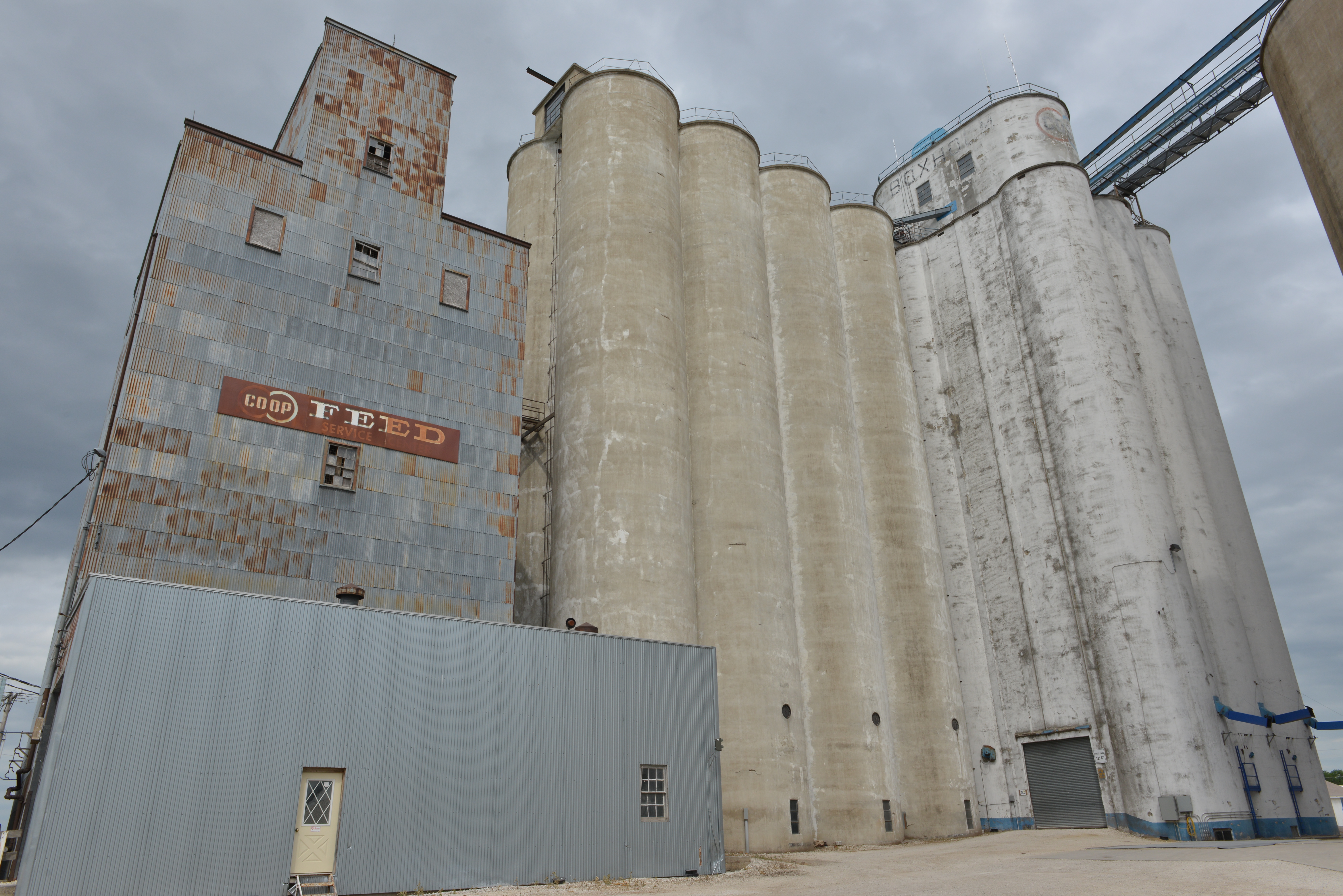
Wide-angle lens distortion is maximized in this view.
At extremely close quarters, the wide-angle lens exaggerates height and adds drama. But the distortion becomes more pronounced.
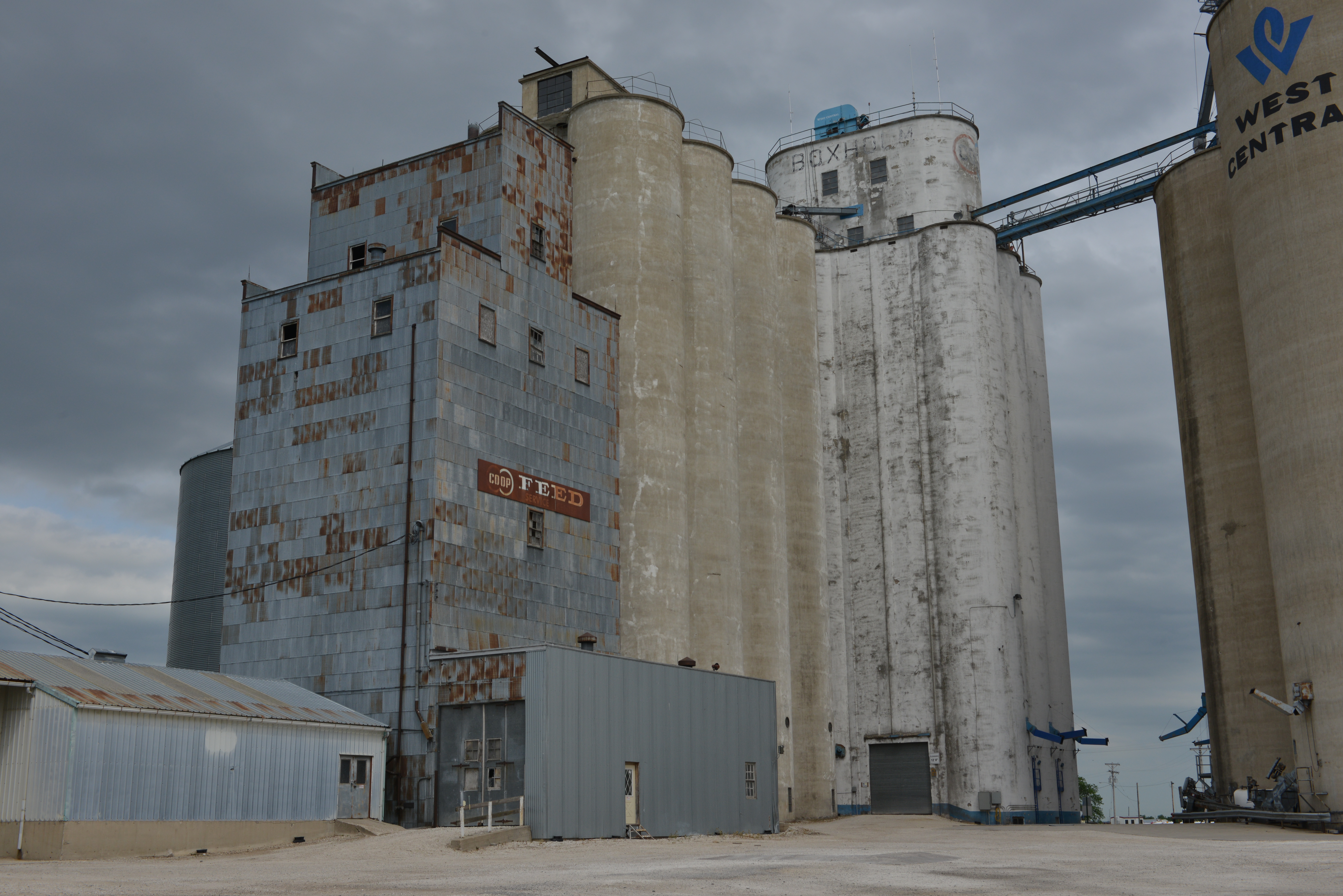
The Tillotson Construction Company of Omaha, Neb., built the elevator in 1955. An annex stands beside it, and an old wooden feed mill is beside that. A much newer elevator with the West Central logo was built later, after it became customary to leave the concrete plain, without the white finish.

A more conventional view of the elevator complex.
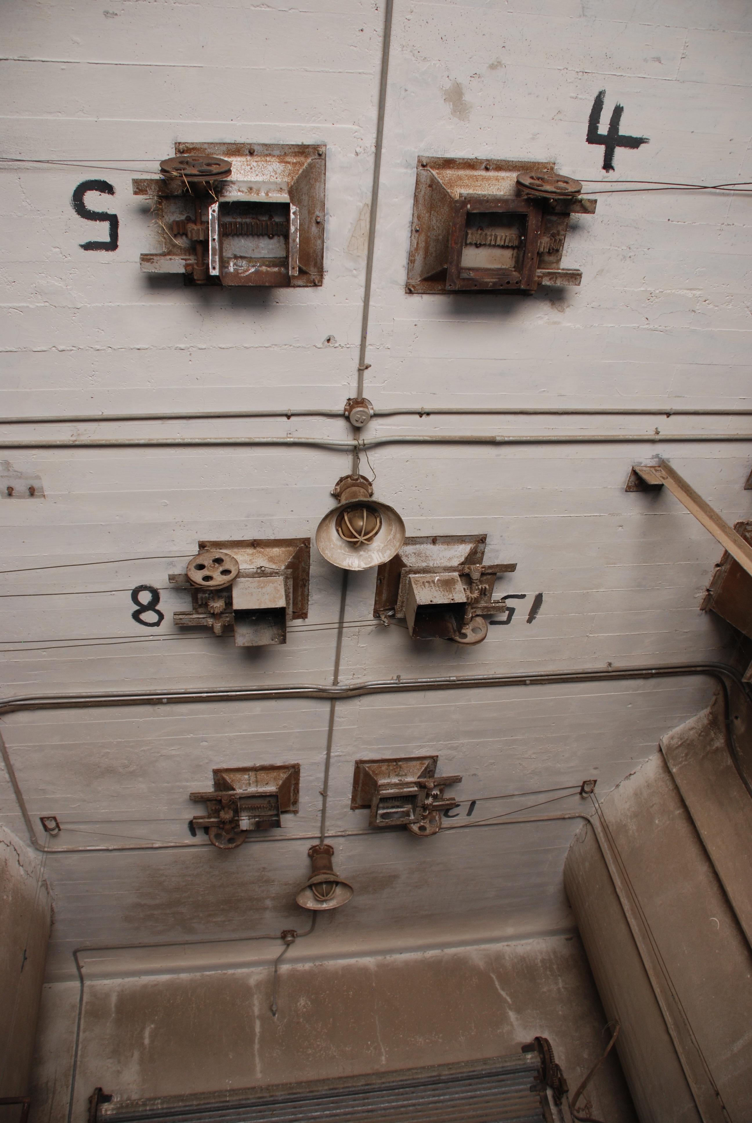
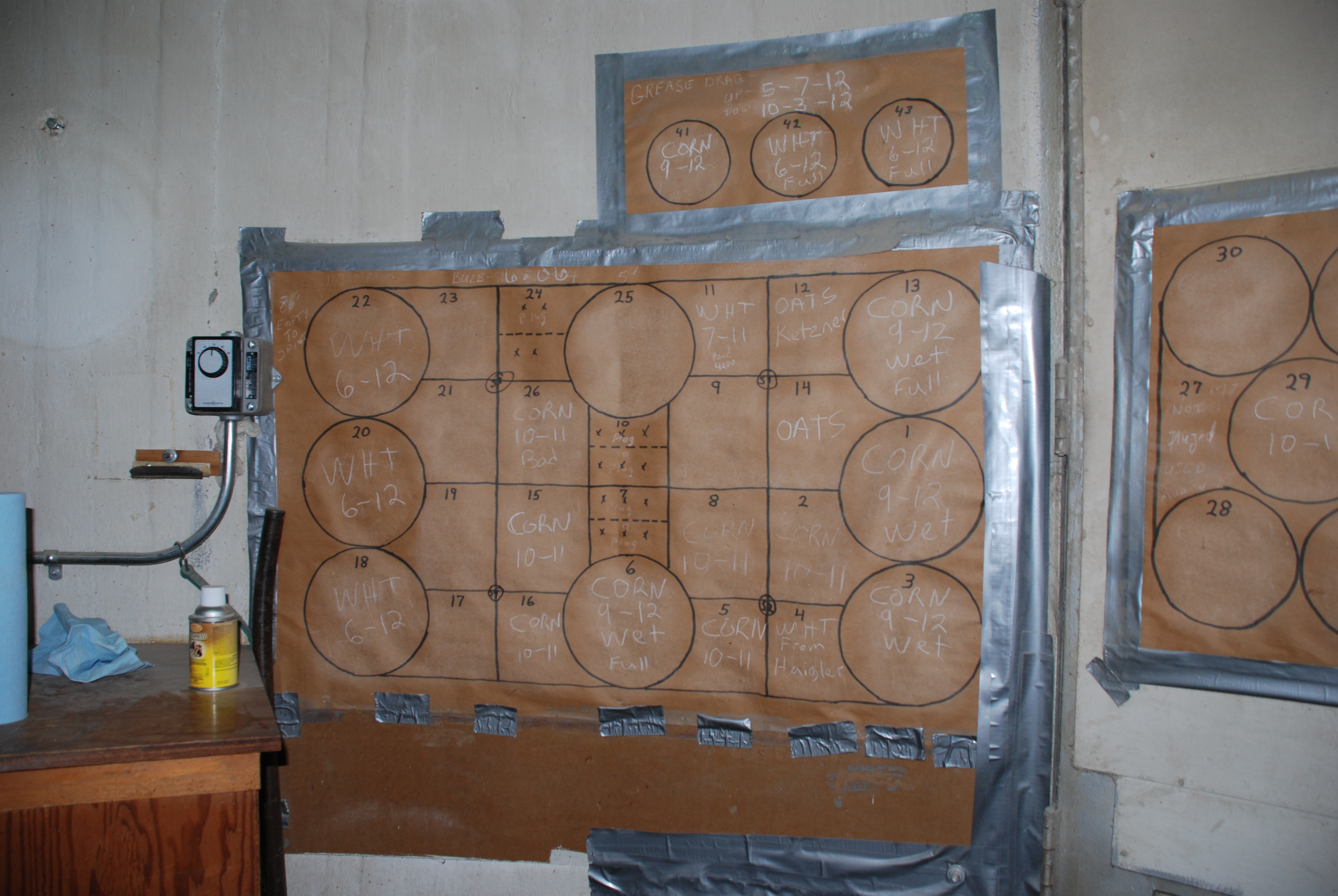
The specifications for the Boxholm elevator are among the Tillotson Company construction records. We learned some details about the elevator from a few stray sources before my visit; for instance, the elevator has exactly 96 light bulbs installed. Its construction followed the Drummond plan. Other projects using the same architectural plan were the elevators at Waverly, Neb., and Lahoma and Drummond, Okla.
Specifications
Capacity per plans (with Dock): 199,400 bushels
Capacity per foot of height: 2,002 bushels
Reinforced concrete per plans (total): 1,797 cubic yards
Plain concrete (3″ hoppers): 33 cubic yards
Reinforcing steel per plans (includes jack rods): 85.71 tons
Average steel per cubic yard reinforced concrete: 95.4 pounds
Steel and reinforced concrete itemized per plans:
Below main slab: 6,861 pounds steel, 59.2 cubic yards concrete
Main slab: 25,603 pounds steel, 202 cubic yards concrete
Drawform walls: 103,192 pounds steel, 1,295 cubic yards concrete
Driveway and Work floor : 3,820 pounds steel, 23.8 cubic yards concrete
Deep bin bottoms (including columns): 7,271 pounds steel, 39.3 cubic yards concrete
Overhead Bin bottoms: 6,040 pounds steel, 27.6 cubic yards concrete
Bin roof and Extension Roofs: 7,210 pounds steel, 41.7 cubic yards concrete
Scale floor (or garner complete): 160 pounds steel, 2.5 cubic yards concrete
Cupola walls (including leg & head): 7,257 pounds steel, 76 cubic yards concrete
Distributor floor: 1,560 pound steel, 9.4 cubic yards concrete
Cupola roof: 2,147 pounds steel, 15.6 cubic yards concrete
Misc. (track sink, steps, etc.): 173 pounds steel, 3.5 cubic yards concrete
Attached driveway: none
Bridge and/or Tunnel: none
Pit Liner–plain: 16 cubic yards concrete
Drier Bin Bottom: 134 pounds steel, 1.3 cubic yards concrete
Coffer Dam, Cleaner Floor: Wood
Remarks: 10 Bin Hot spot; 8 Bin Aeration tubes; Dryer bin
The rounded headhouse is a reliable indicator of a Tillotson elevator
Construction details
Like Waverly: construction details were identical to Waverly and not listed separately in the records.
Main slab dimensions (drive length first dimension): 56 1/2′ x 70′
Main slab area (actual outside on ground): 3,850 square feet
Weight reinforced (total) concrete (4000 pounds per cubic yard plus steel): 3,747 tons
Weight plain concrete (hoppers; 4000 pounds per cubic yard): 98 tons
Weight hopper fill sand (3000 pounds per cubic yard): 732 tons
Weight of grain (at 60 pounds per bushel): 5,982 tons
Weight of structural steel and machinery: 20 tons
Gross weight loaded: 10,579 tons
Bearing pressure: 2.75 tons per square foot
Main slab thickness: 24″ with 3″ pile cap
Main slab steel: straight #9 at 7″ spacing
Tank steel and bottom (round tanks): #4 at 12″ spacing
Lineal feet of drawform walls & extension: 606′
Height of drawform walls: 120′
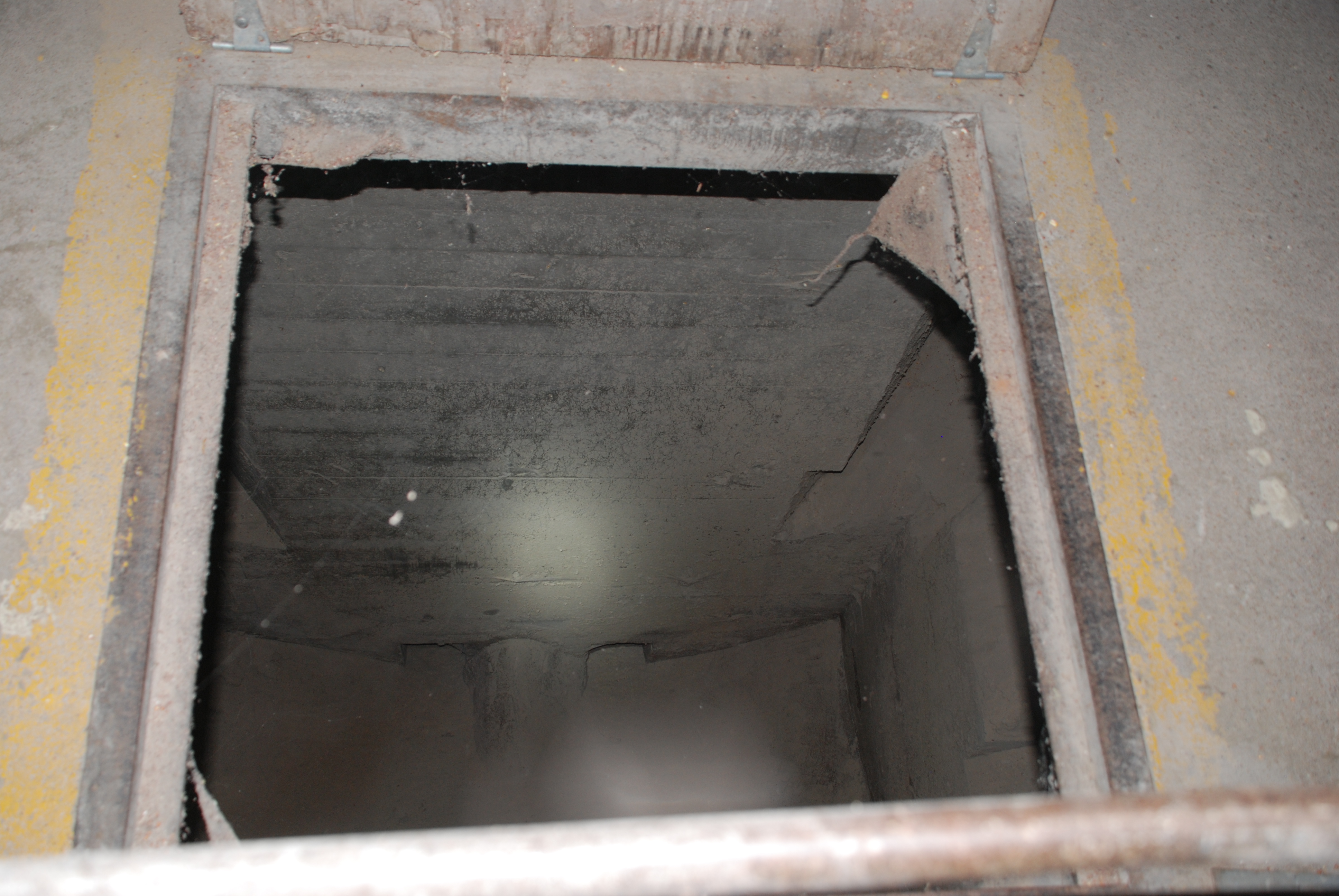
Pit depth below main slab: 15’3″
Cupola dimensions (outside width x length x height): 22 1/4′ x 48 1/2′ x 35′
Pulley centers: 160.75′
Number of legs: 1
Distributor floor: yes
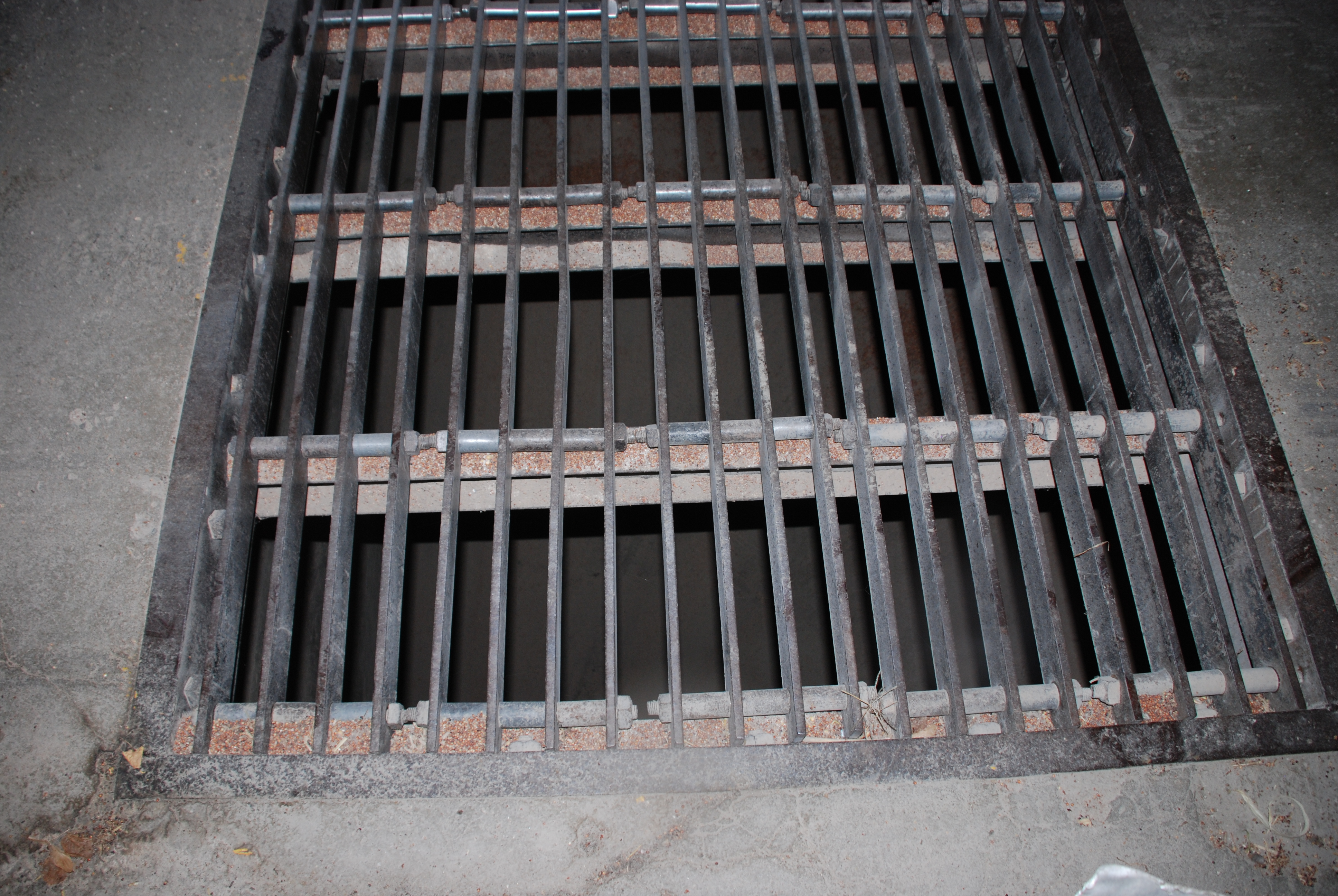
Track sink: yes
Full basement: yes
Electrical room: yes
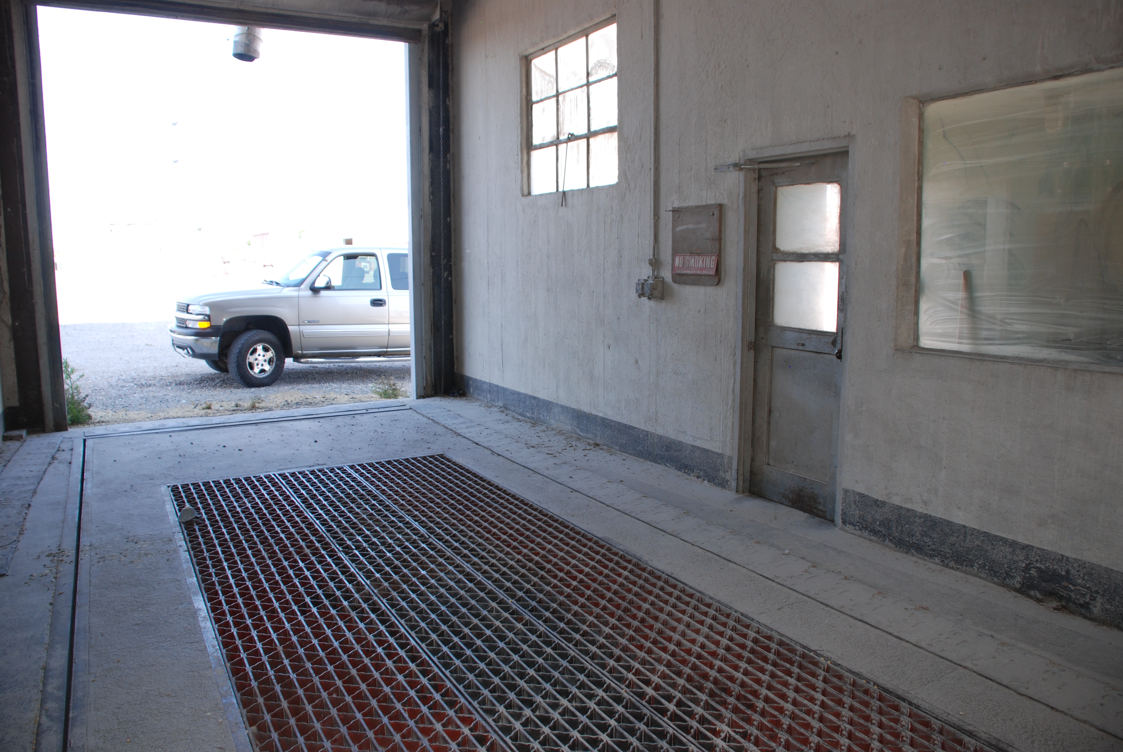
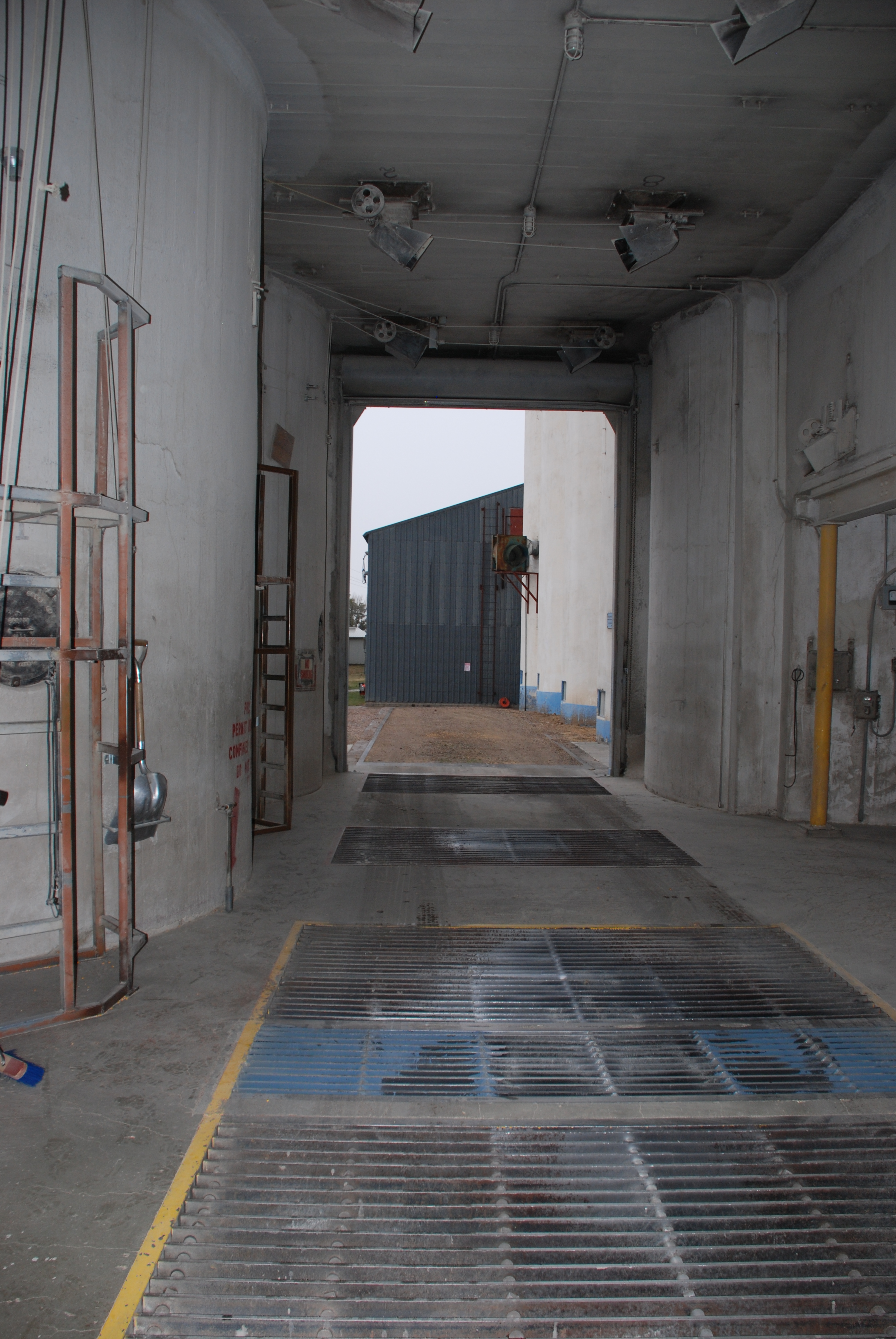
Driveway width clear: 13′
Dump grate size: 2 at 9′ x 5′ and 9′ x 15′
Column under tanks size: 16″ square
Boot legs and head: concrete
 Machinery details
Boot pulley: 72″ x 14″ x 4 15/16″
Head pulley: 72″ x 14″ x 2 7/16″
R.P.M. Head pulley: 42
Belt: 335′, 14″ 6 ply Calumet
Cups: 12″ x 6″ at 8″ spacing
Head drive: Howell 40 horsepower [4 circled here]
Theoretical leg capacity (cup manufacturers rating): 8,440 bushels per hour
Actual leg capacity (80% of theoretical rating): 6,750 bushels per hour
Horsepower required for leg (based on actual capacity): 32 horsepower
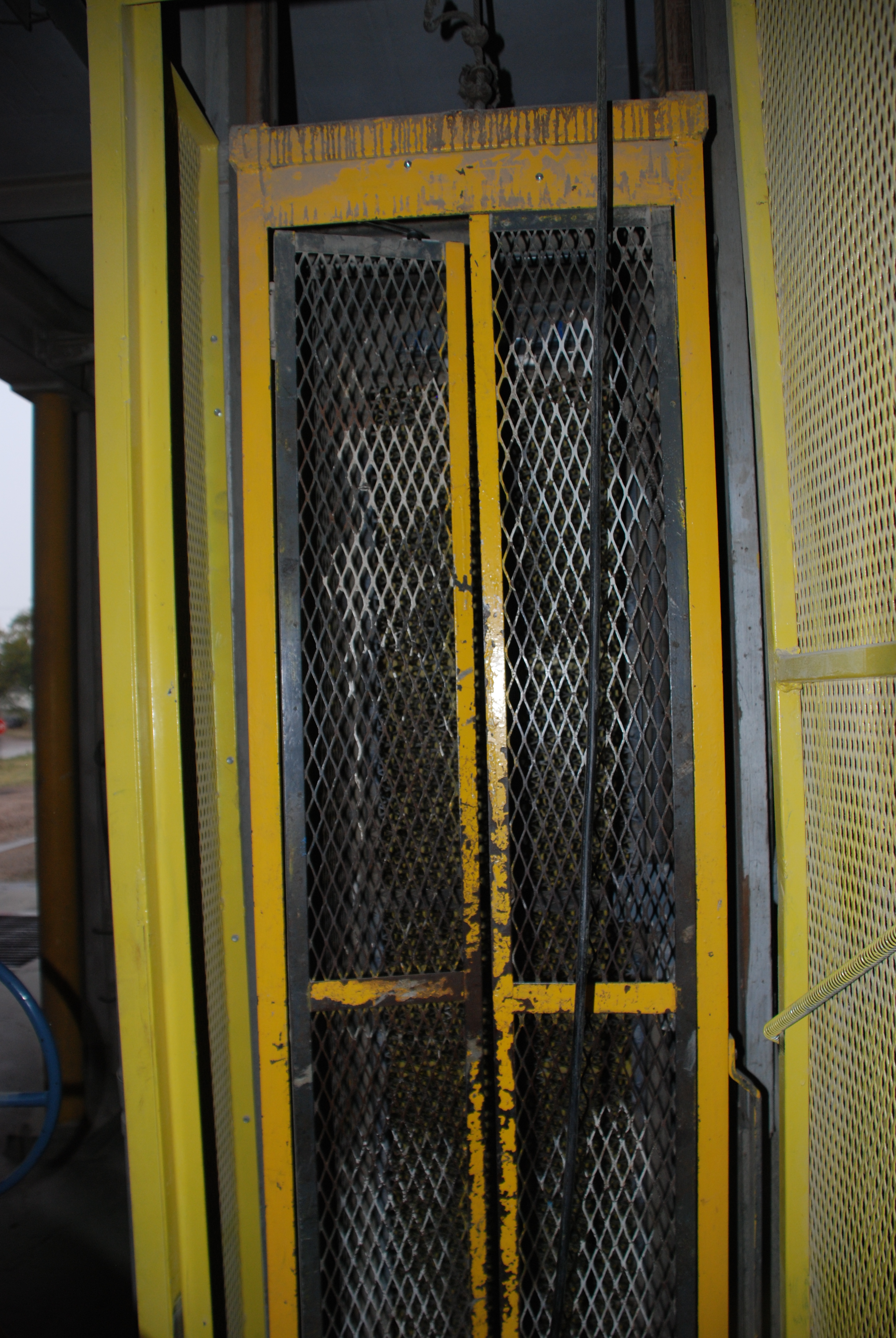
Man lift: 1 1/2 horsepower Ehr.
Load out scale: 25 Bushel
Load out spout: 10″ diameter
Truck lift: 7 1/2 horsepower Ehr.
Dust collector system: Fan to bin
Cupola spouting: 10″ diameter
Driveway doors: 2 overhead rolling
Conveyor: provision
Remarks
see page 10 (above)


 Story and photos by Kristen Cart


 An elevator built by Quad States was added to the


 It is enlightening to see an elevator complex in person and compare it with an early photograph. The changes wrought in almost seventy years can be surprising, but even more unexpected can be the features that remain the same.
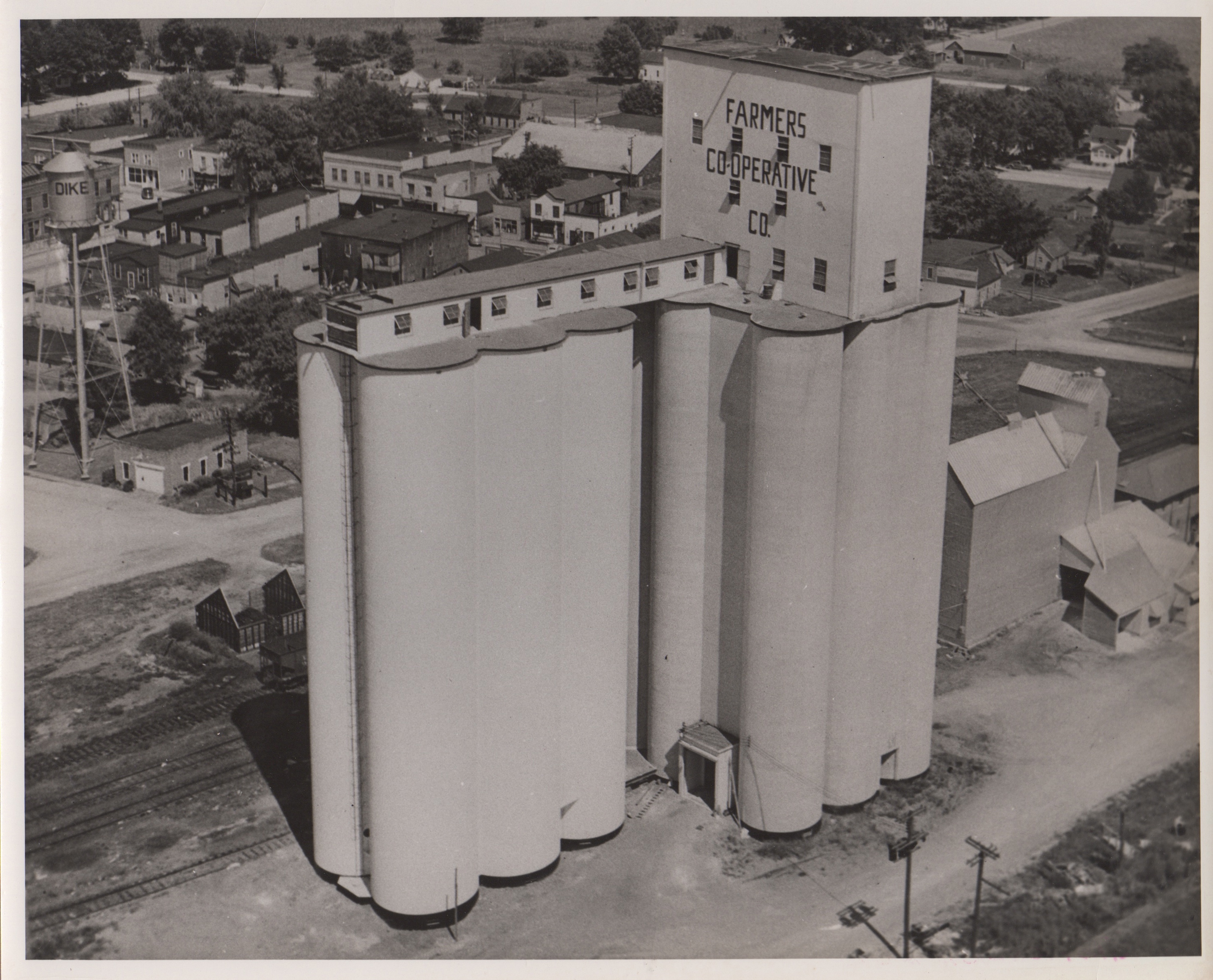
 Tillotson Construction arrived on scene in 1949 to add the annex just three years after the main house was built. In the late 1940s, when elevators were filled just as fast as they could be built, annexes sprung up almost before the concrete cured on the original elevators.


 This situation would require some investigation, but not on a day when I had to get home, with another 400 miles or so to go. I had at least one more stop planned to see an elevator, at Ralston, a town just a few miles further east, and my three kids tolerated the stops, hanging in there at the frazzled edges of their patience.
 I didn’t count on being able to date the demolition, but the map’s “street view” came to the rescue. An


