Insights from a Ralston, Iowa, elevator maintenance worker

DSC_5966

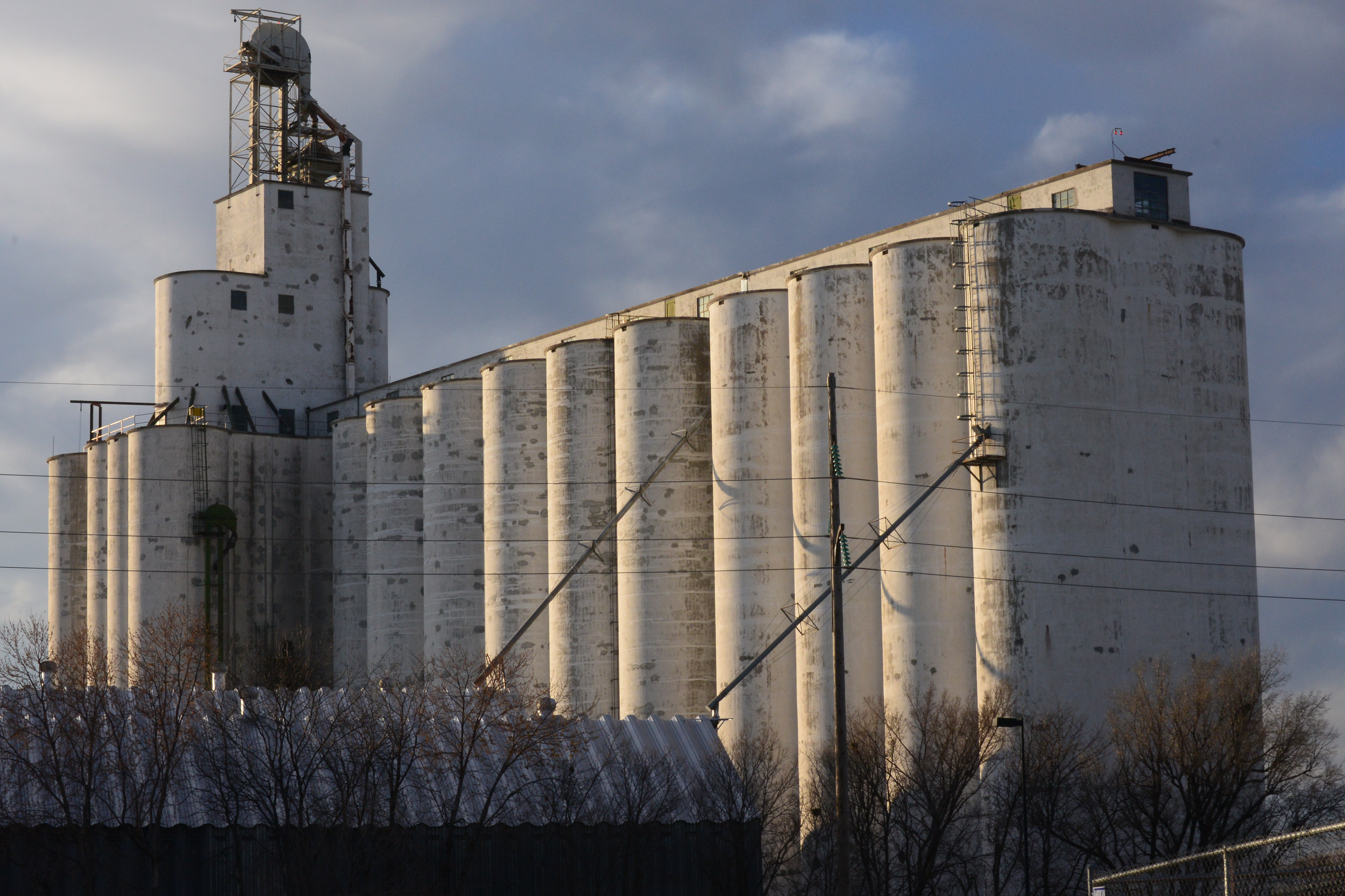
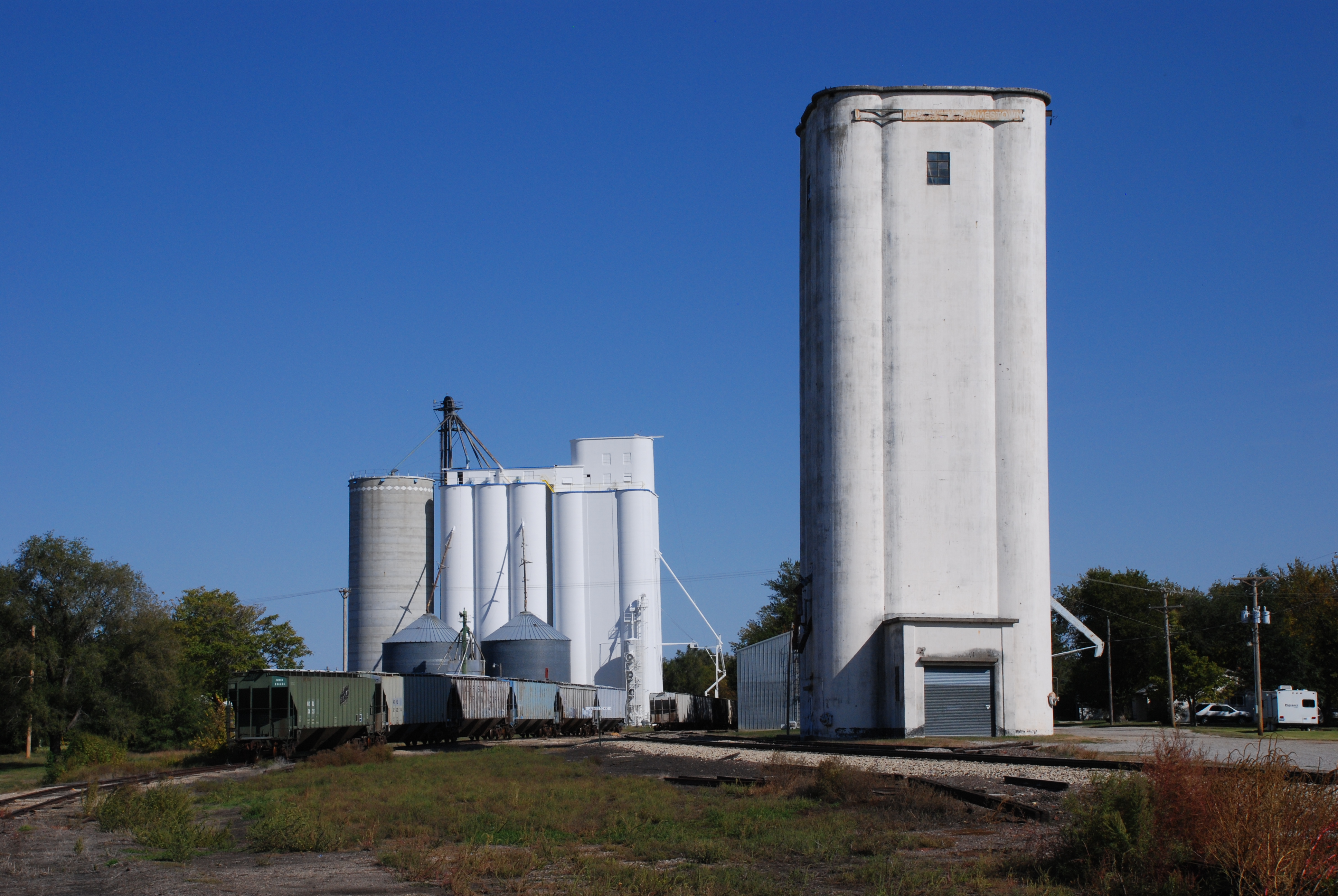
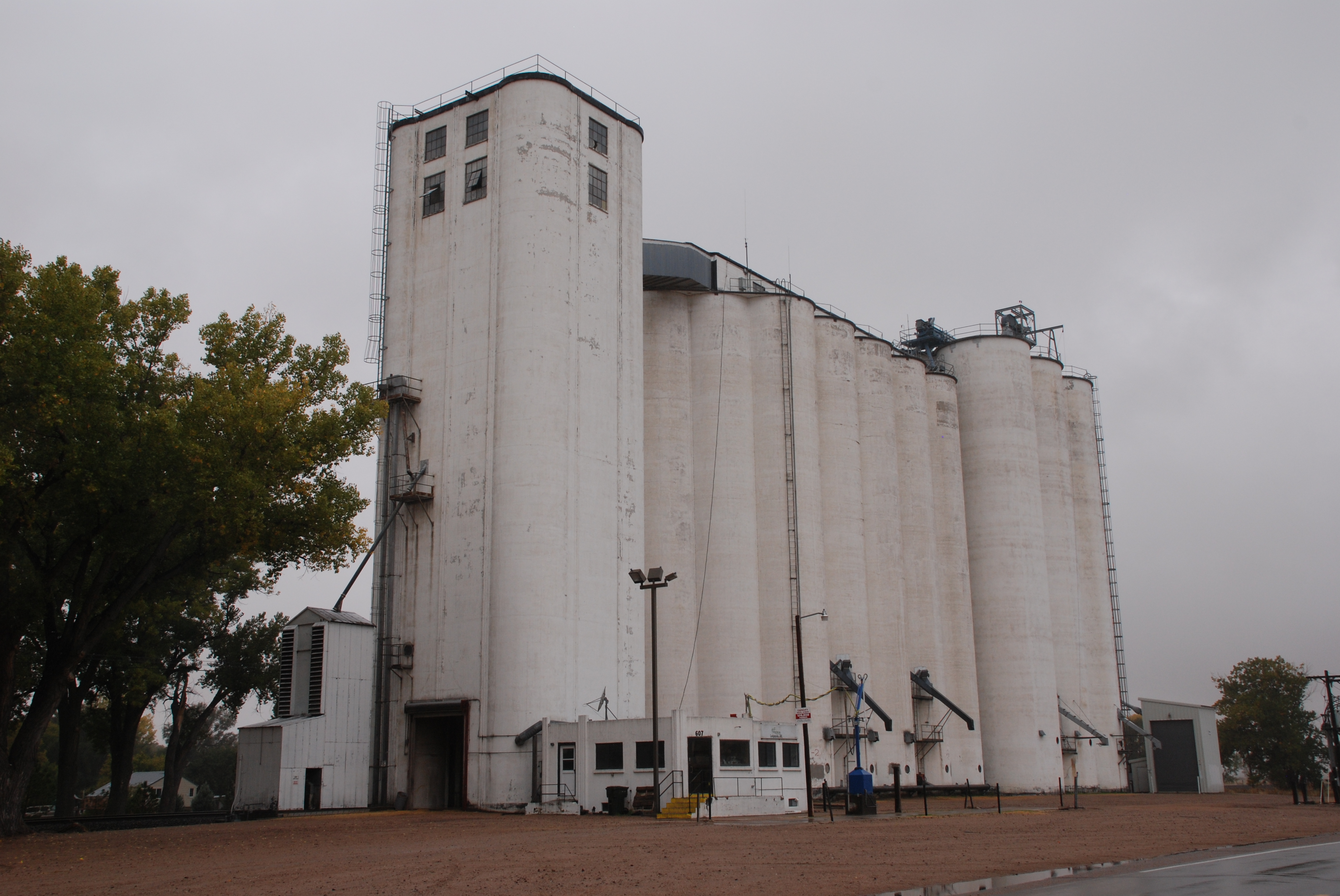
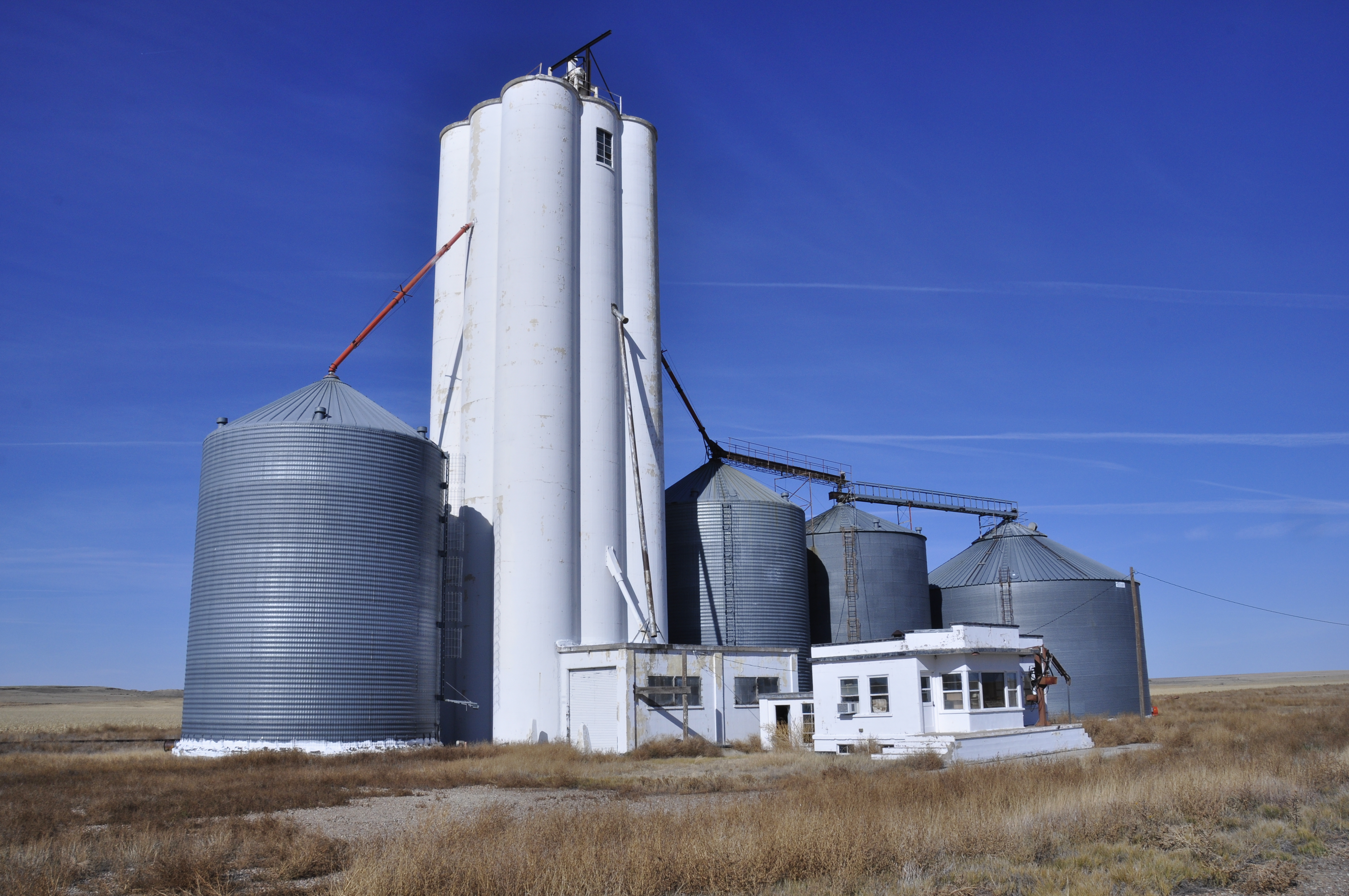
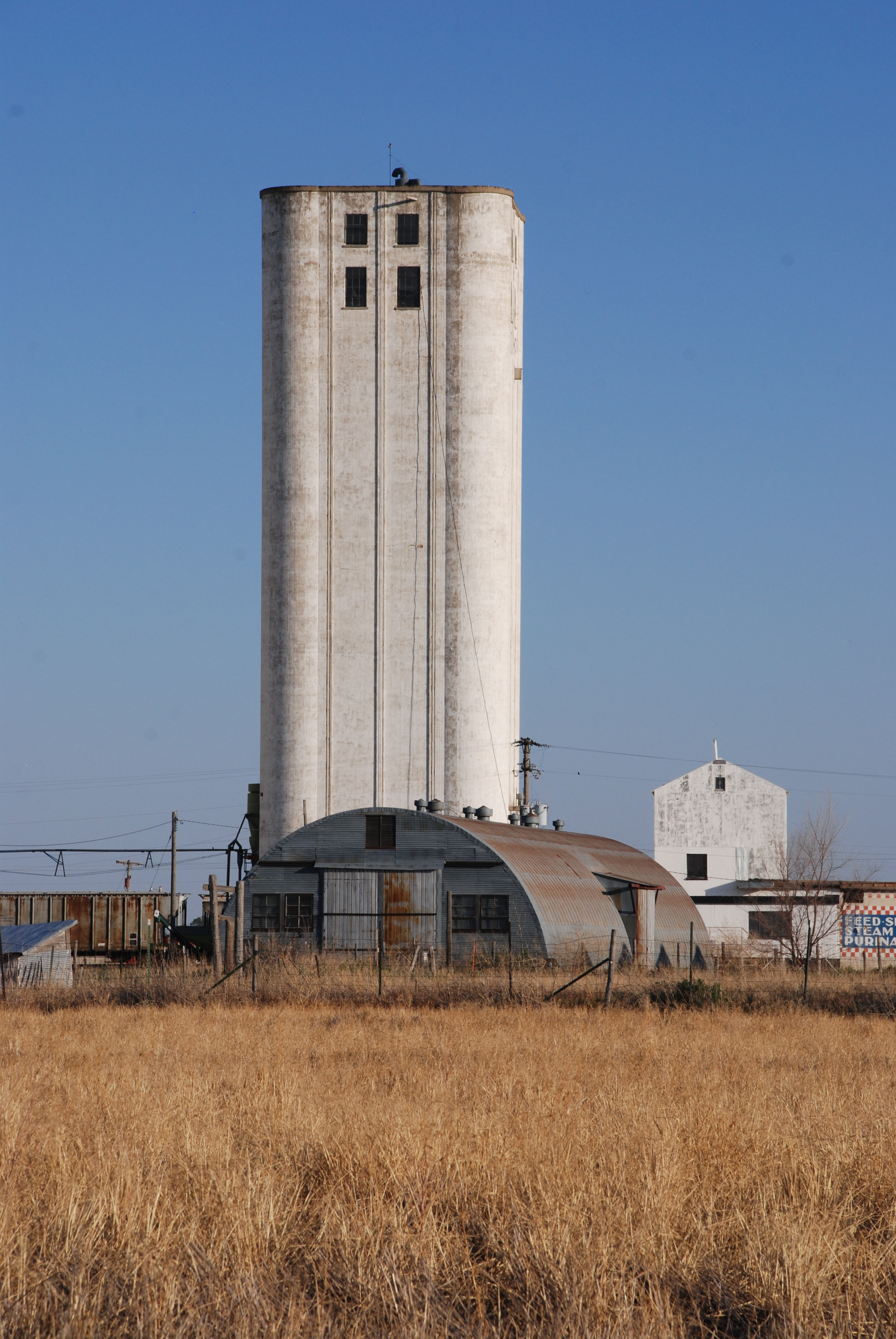
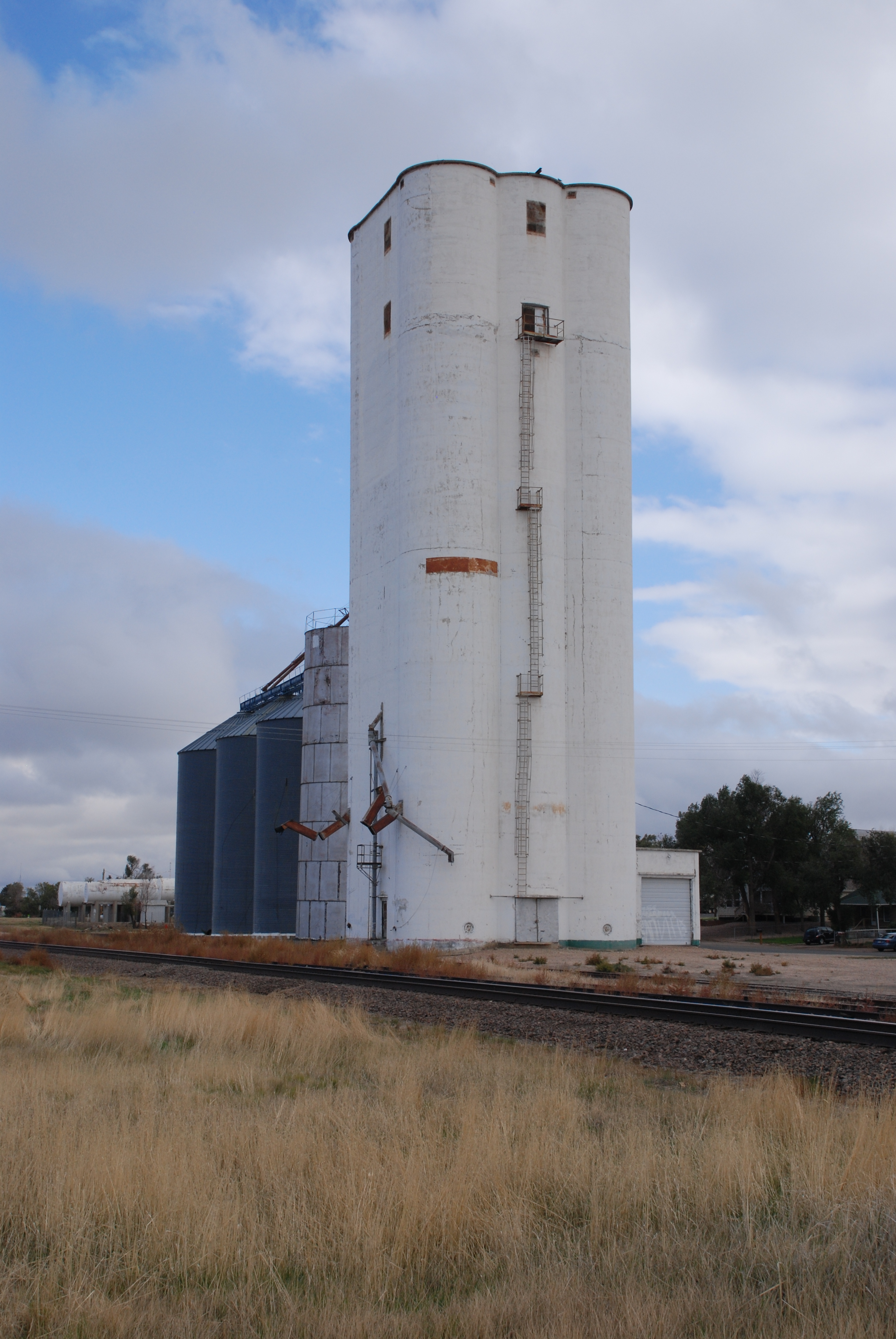
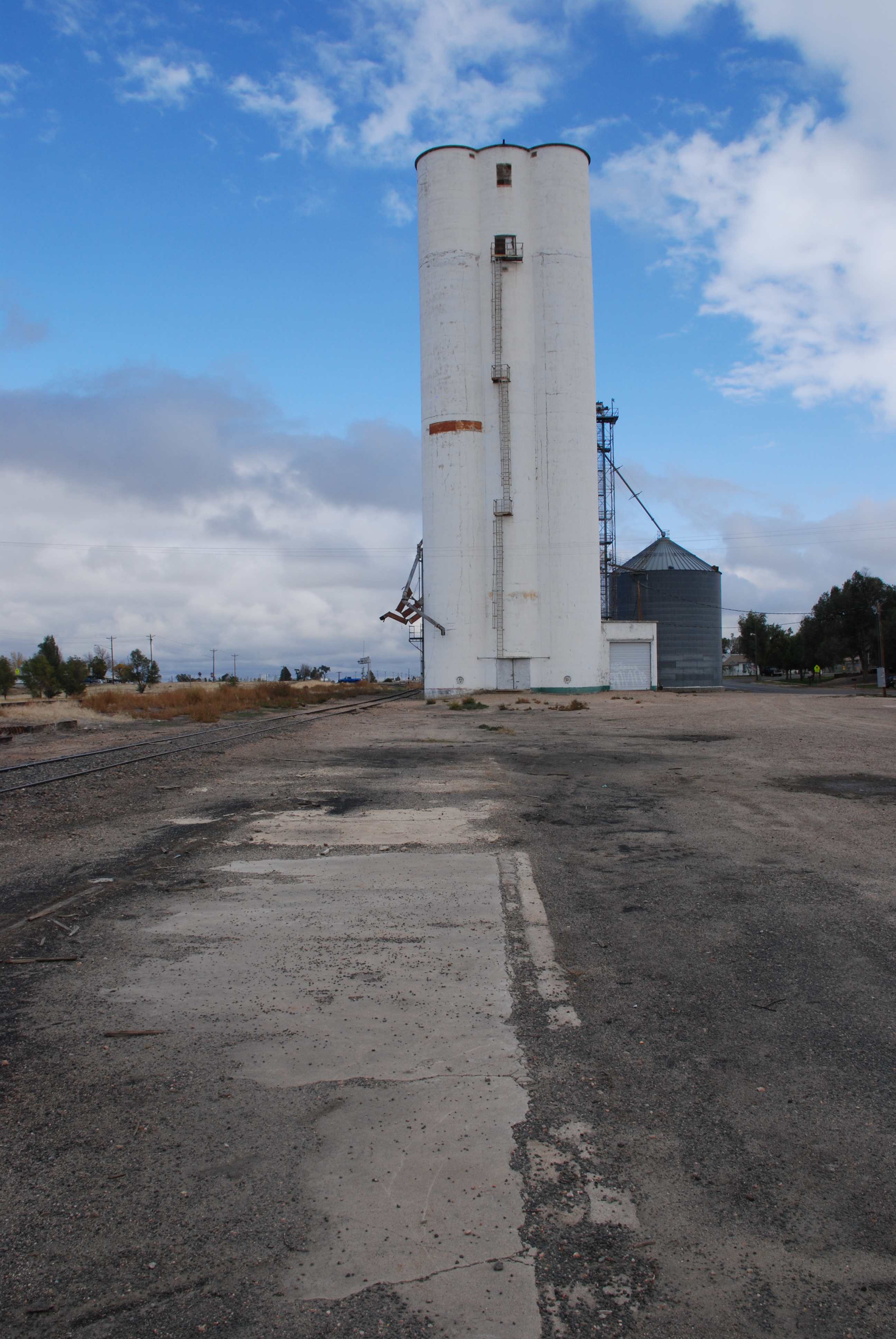
At the far left edge of the photo, the annex can be seen behind the similarly sized elevator.

Story and photos by Kristen Cart

Each time we travel to Nebraska to see our family, I try to investigate elevators, and the kids groan and roll their eyes, pulling electronic entertainment out of their backpacks.

In March, our trip home warranted a stop at Ralston, Iowa, where we hoped to see an annex built by Tillotson Construction Company of Omaha as we trekked eastbound along U.S. Highway 30. Ralston is about midway across the state and lies south of the highway, and is the site of one of the projects documented in Tillotson company records.

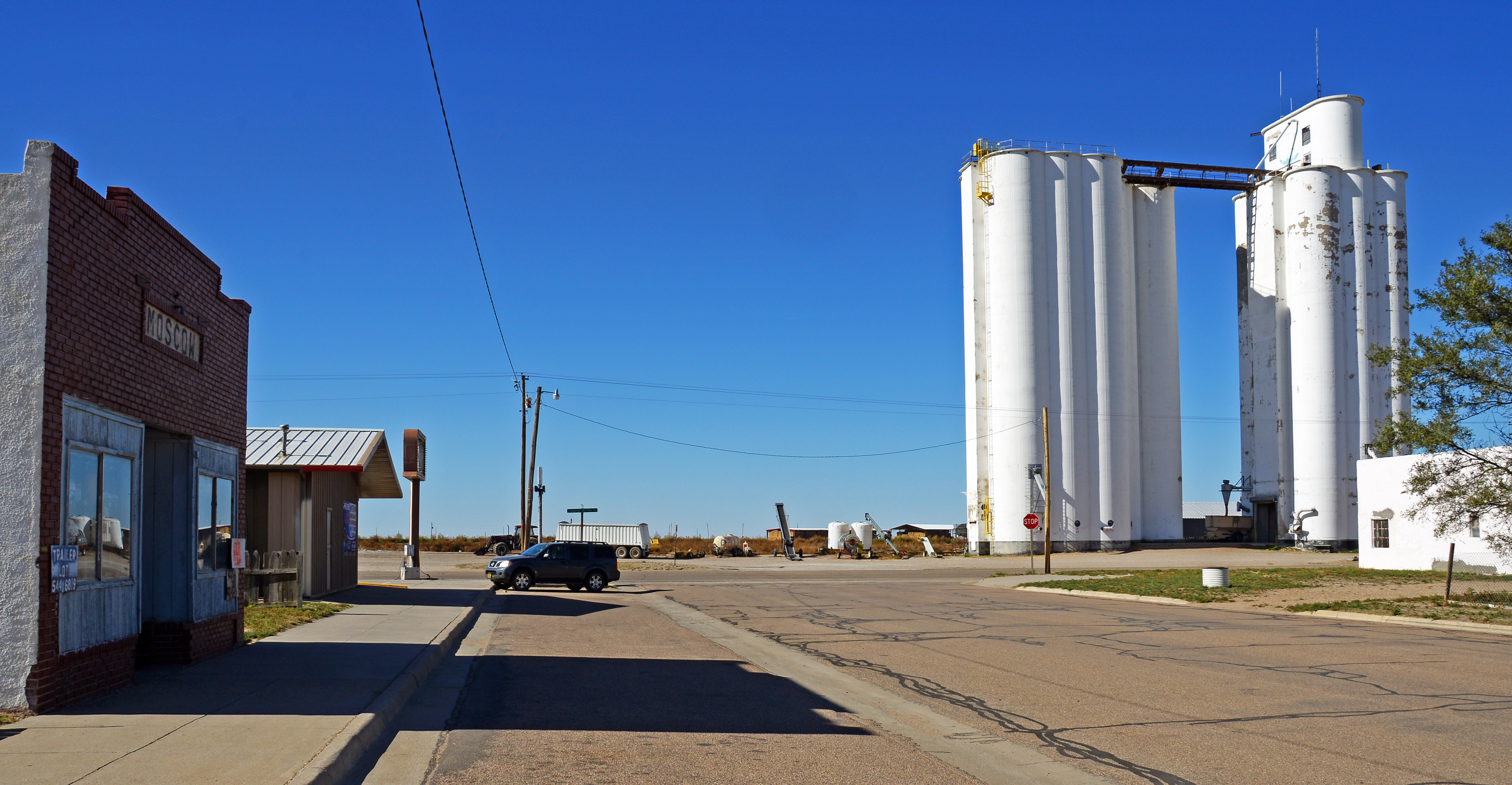
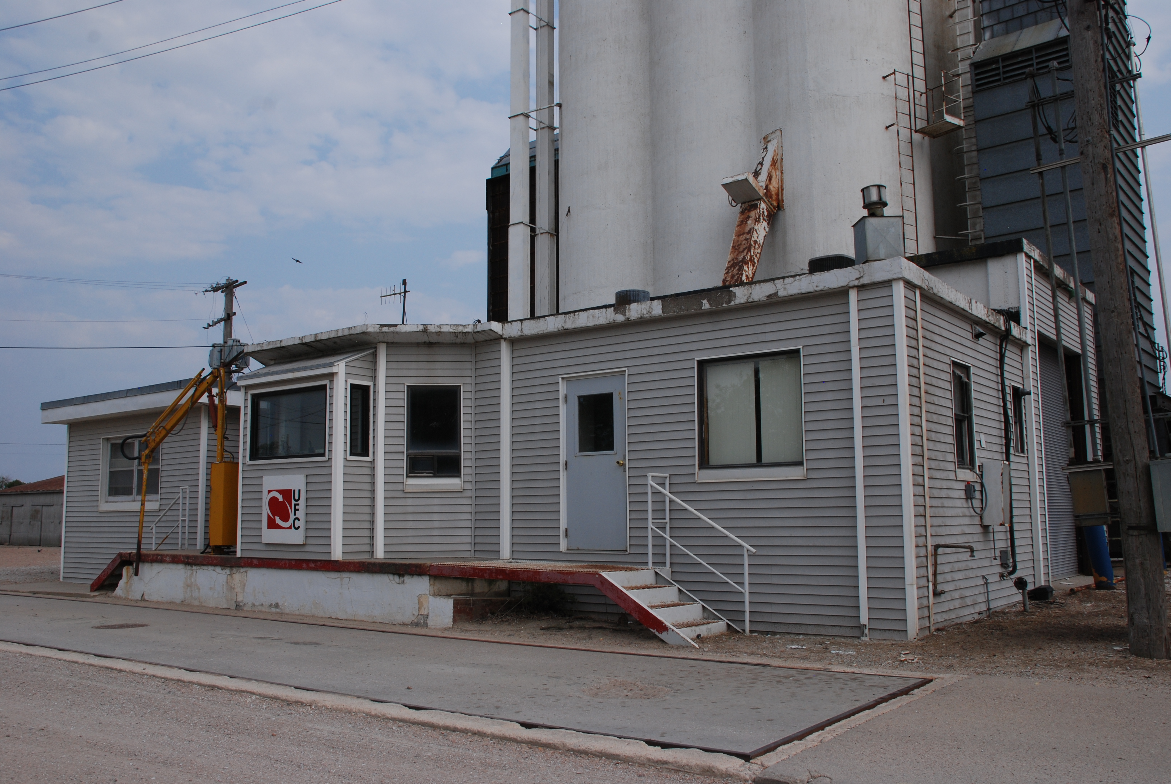
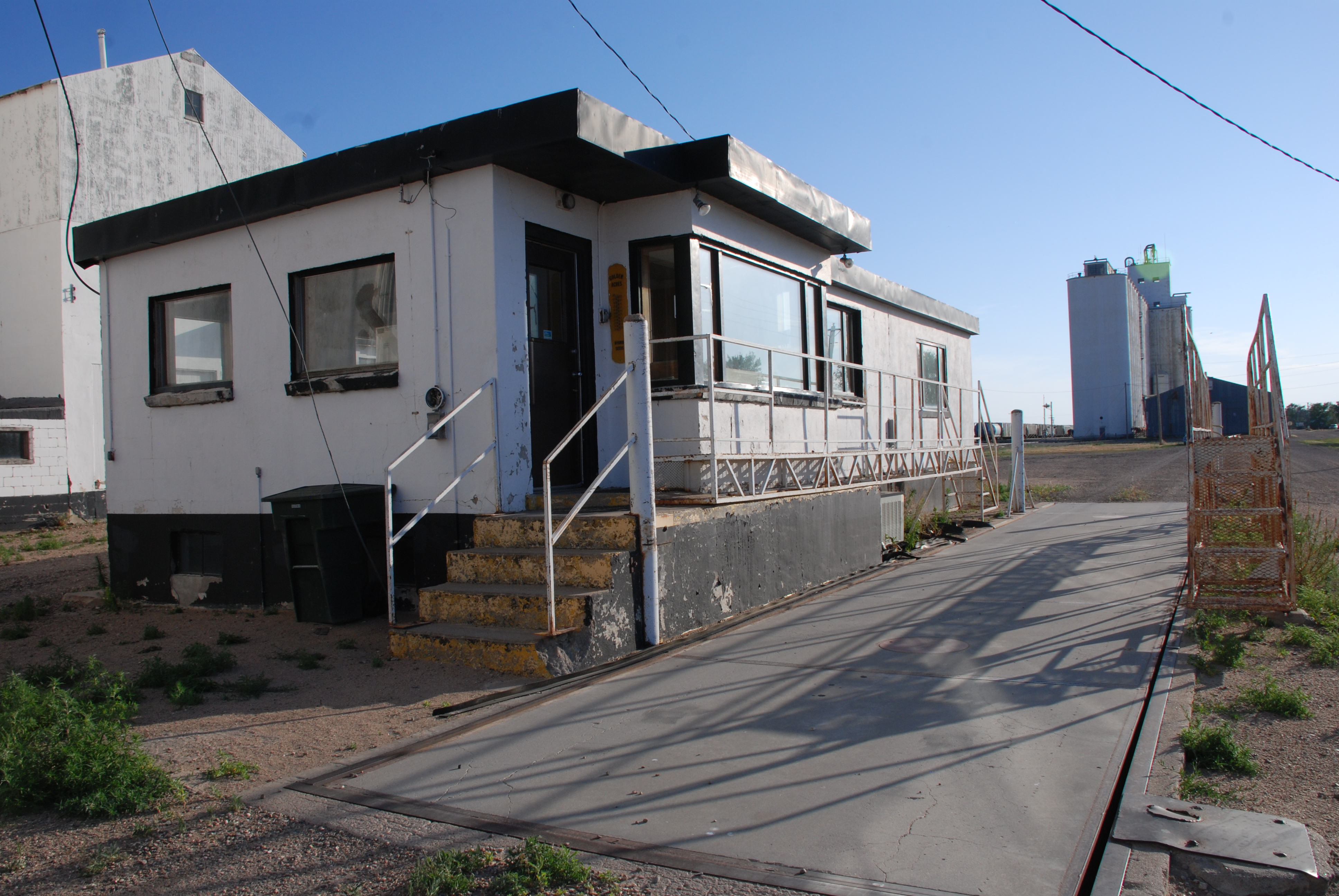
The West Central Cooperative elevator complex, silent and lofty, rimmed the edge of town as we approached on a bright Sunday afternoon. Not a soul was in sight as we entered the parking lot near the cooperative headquarters. But a car in front of the office building was open with a shopvac beside it. Someone had to be around.

DSC_6016

A much larger group of elevators was behind me, away from the town, as I took the photo.

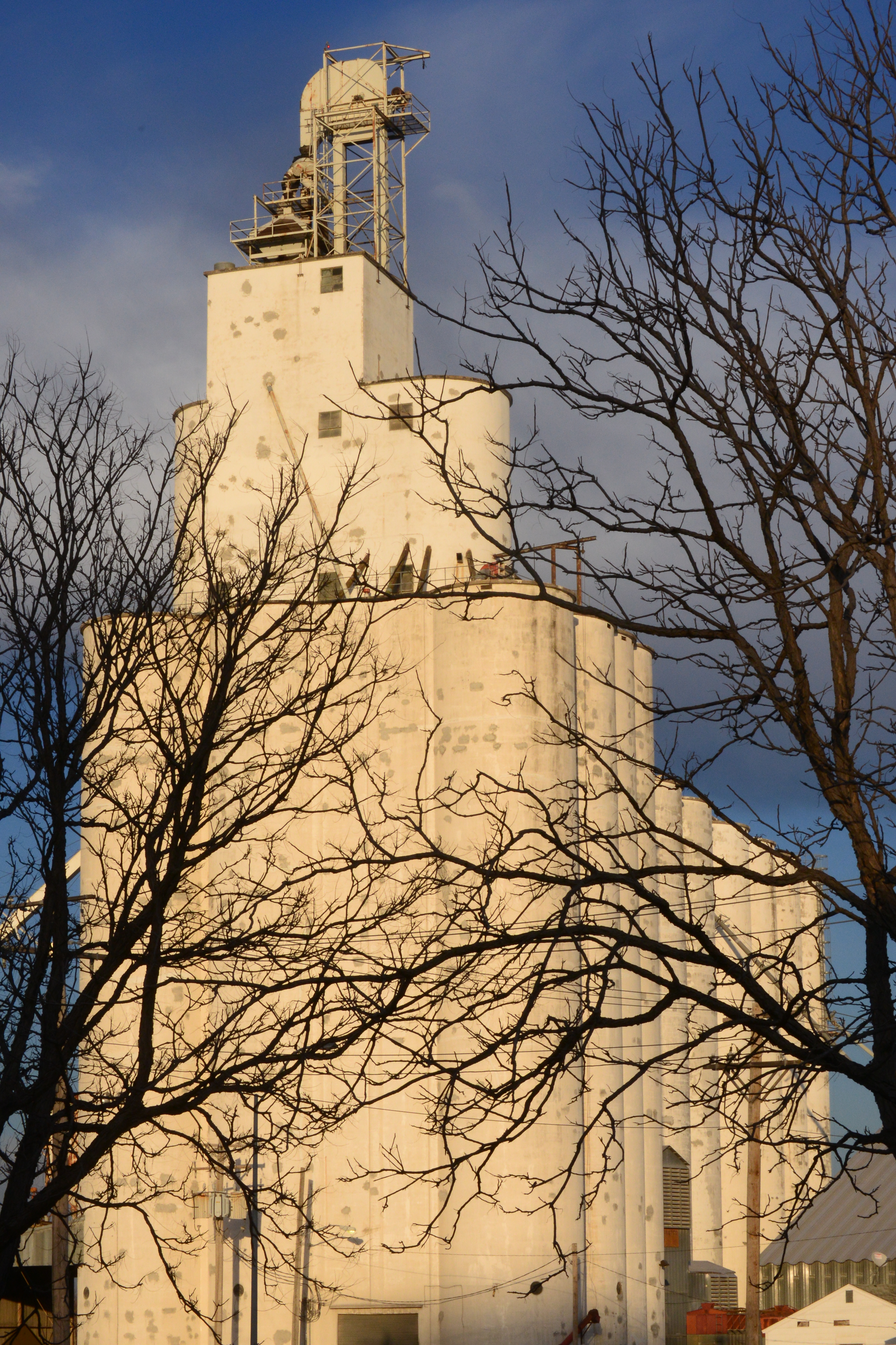
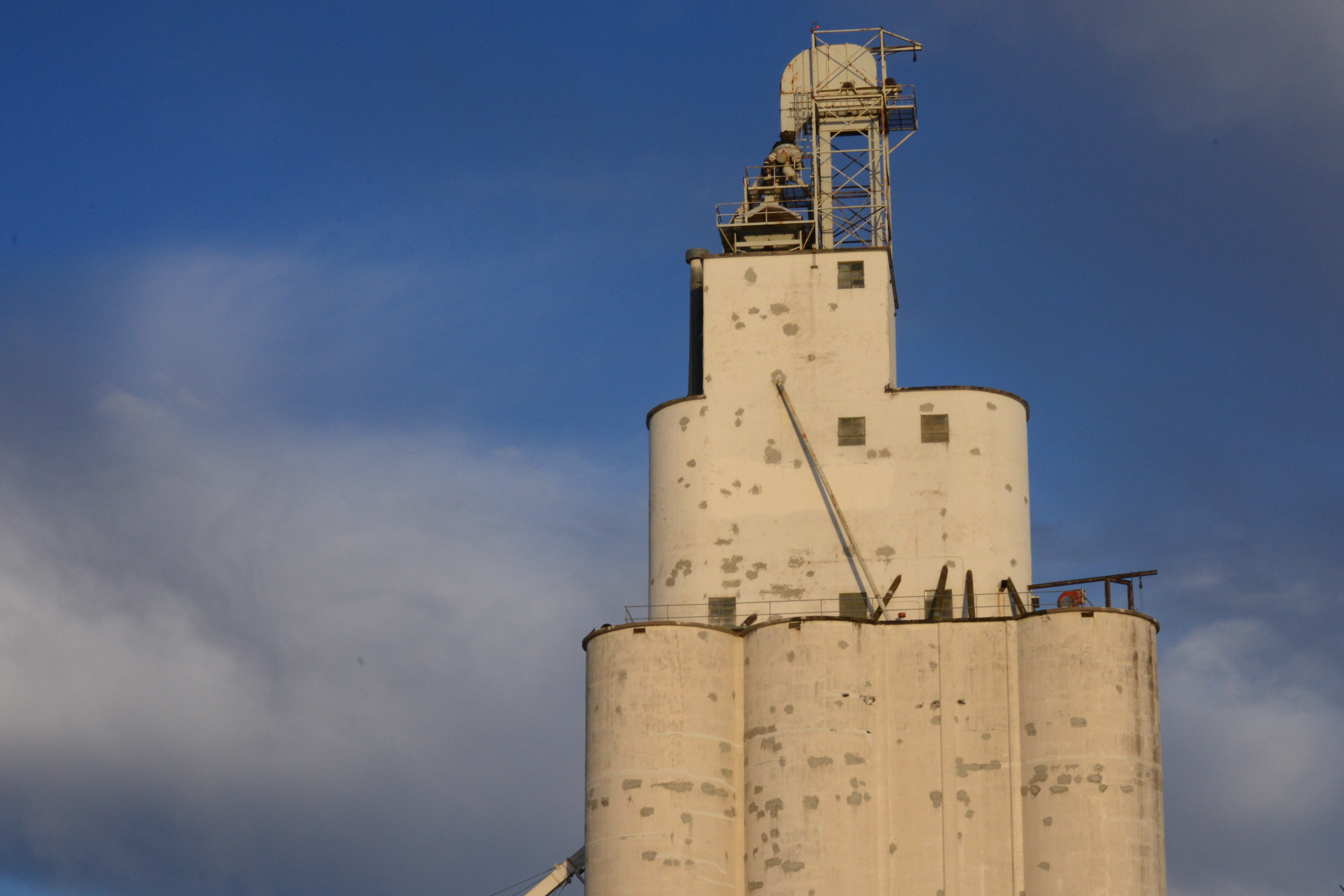
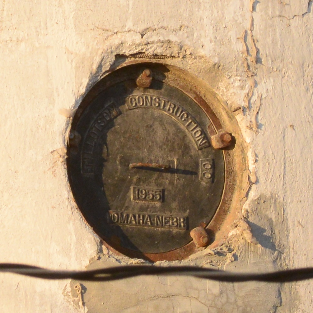
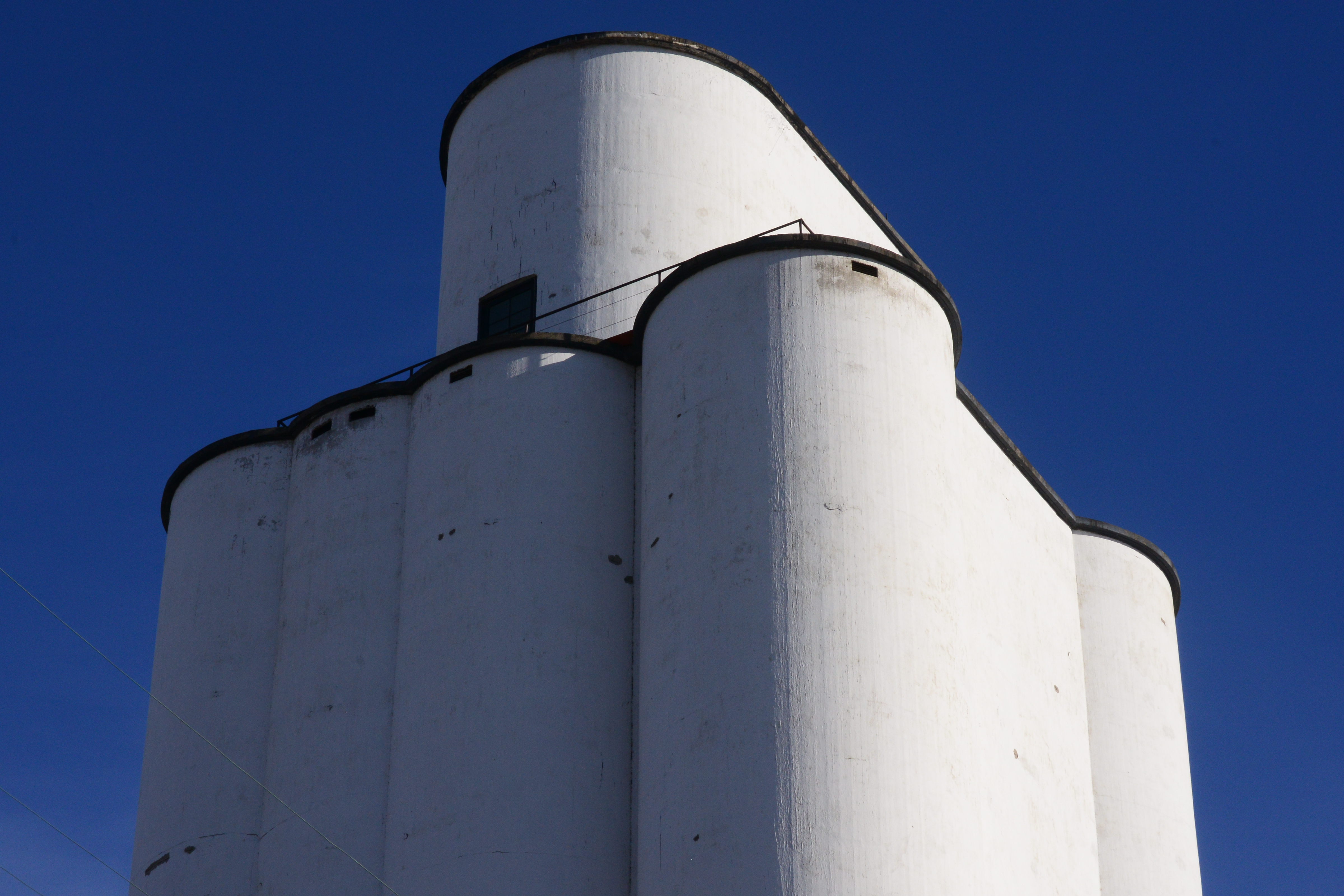
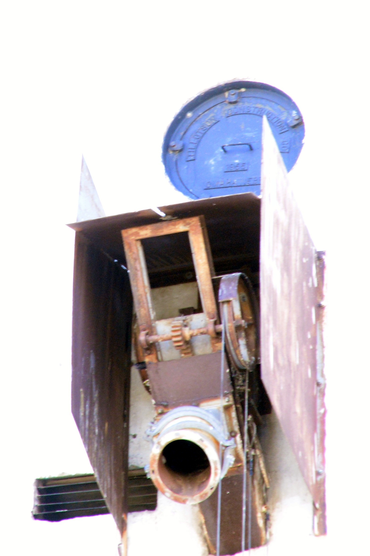
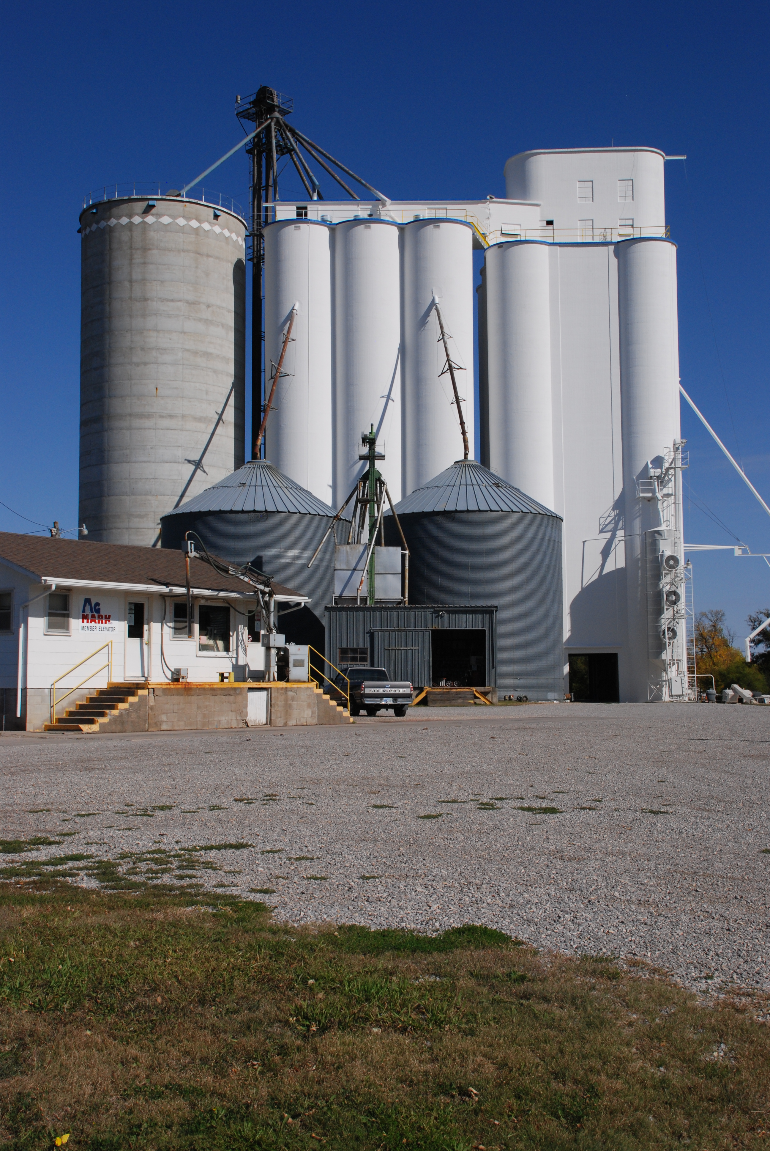
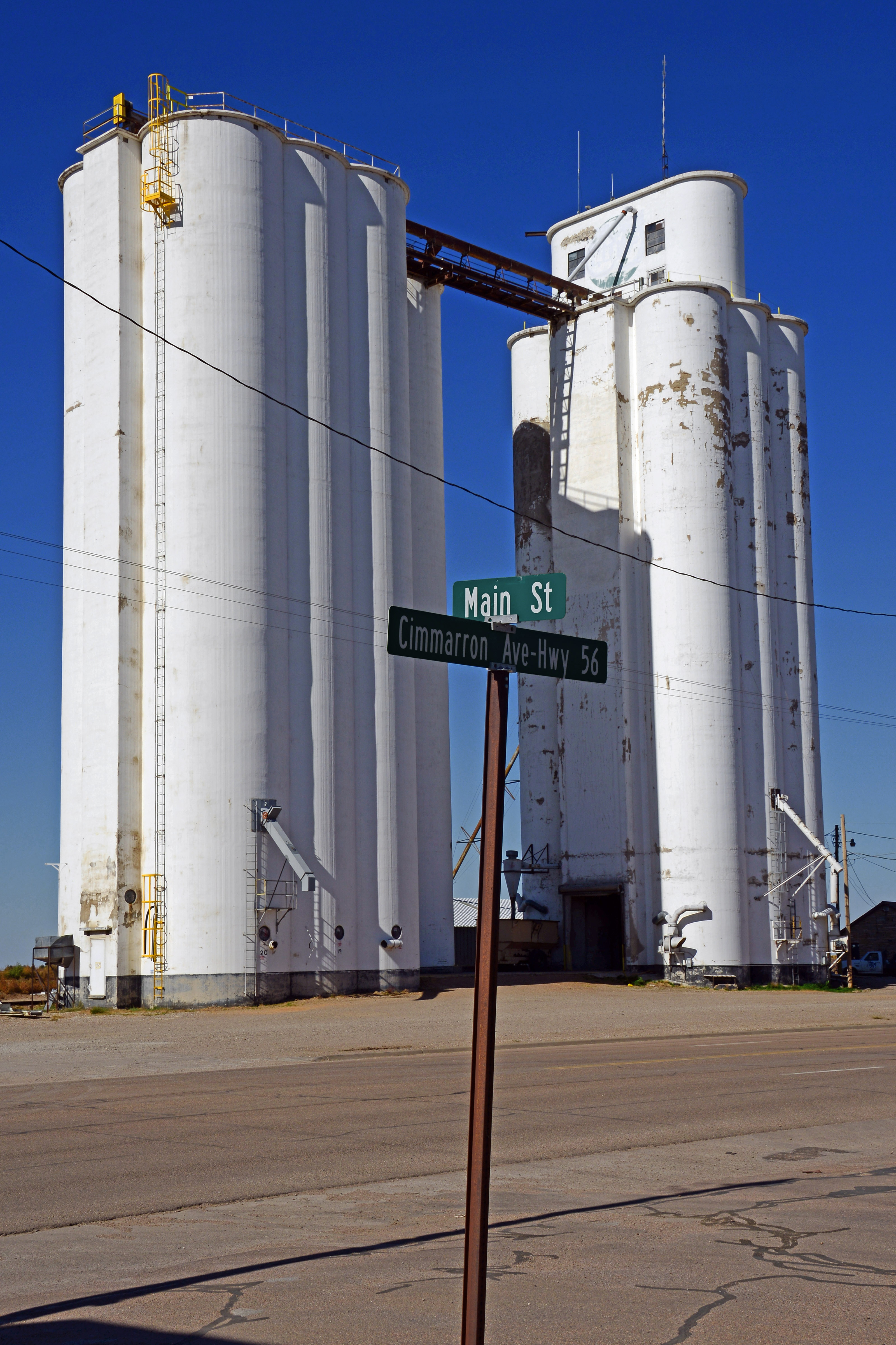
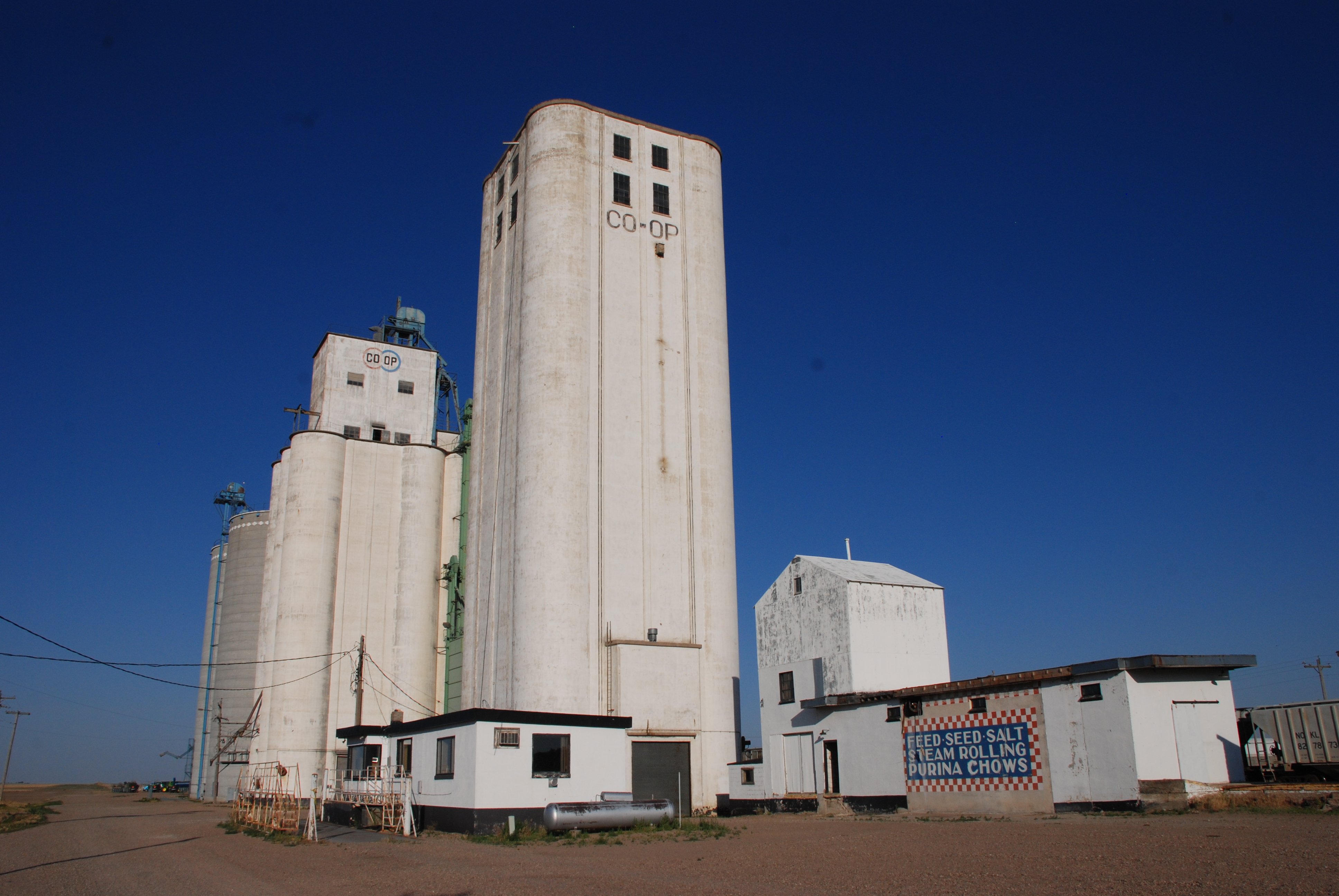
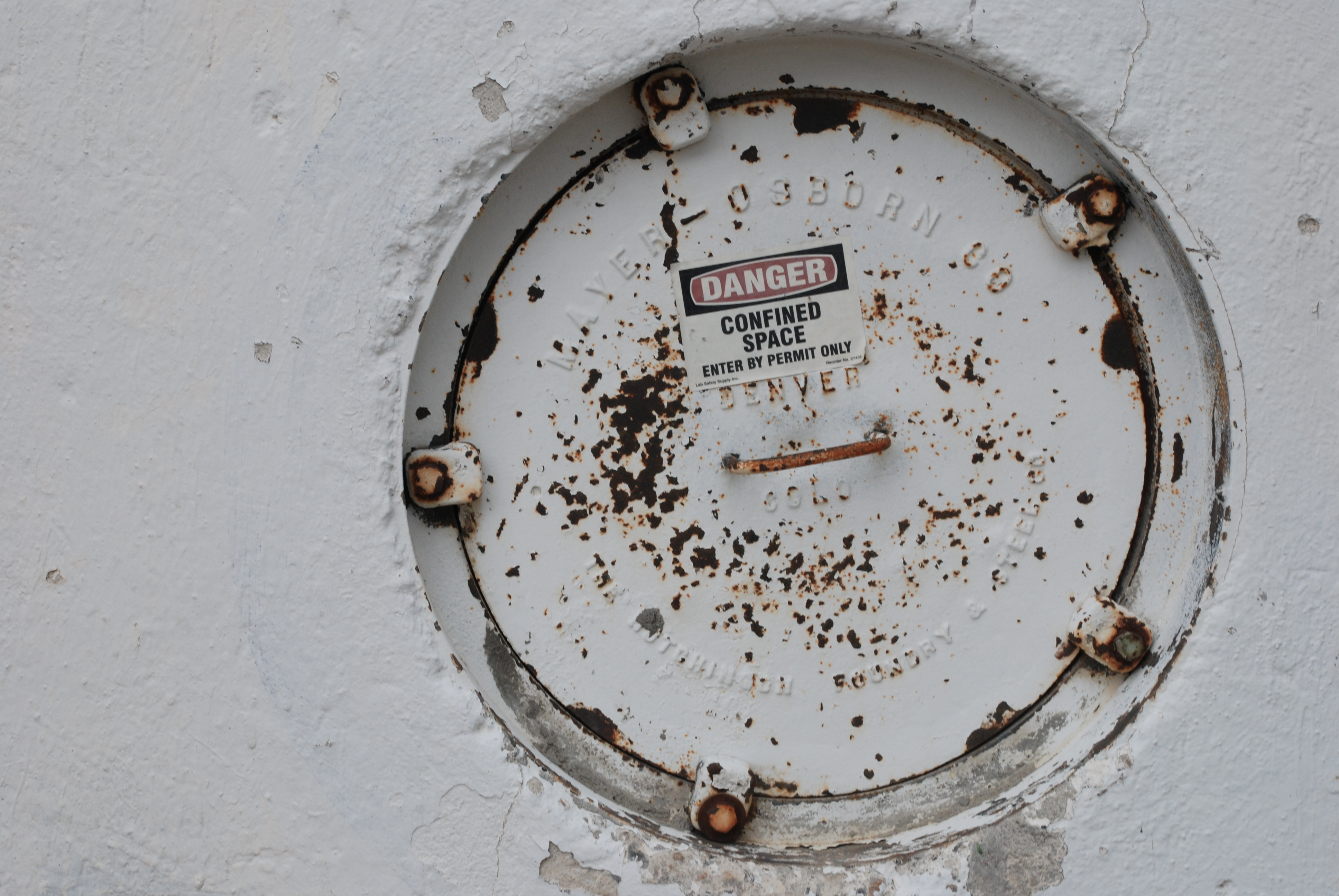
The elevator group in Ralston is dominated by a large squarish elevator, a multi-bin elevator, and a large, multi-bin, rectangular annex snugged in beside the latter. Between the first elevator and the second is an old wood elevator which immediately attracted my attention. It made a fine photographic subject. While shooting the scene, I looked for signs of a Tillotson project. Nowhere was there any manhole cover with the name of a builder. And no one was present who could give me a look inside.

The annex, slightly narrow than the elevator, is on the left

The annex, slightly narrower than the elevator, is on the left.

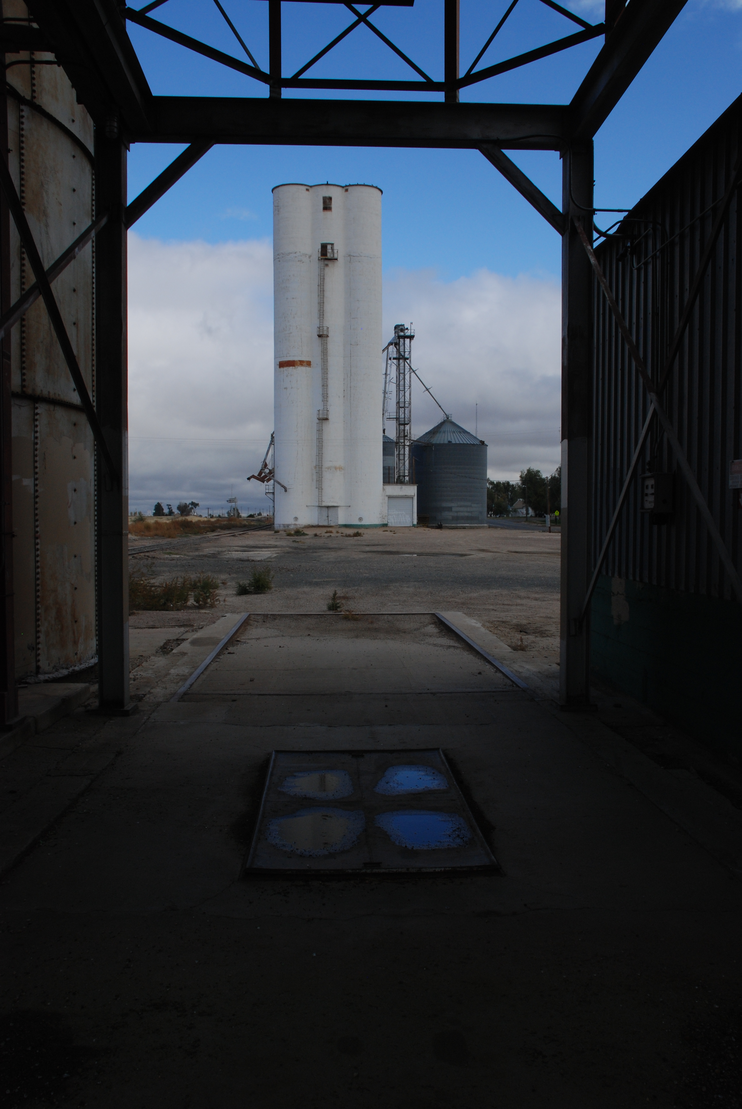
In fact, the deserted elevator group so dominated the town, along with its companion group of elevators a mile or so down the tracks, that it seemed intimidating to go near it. So I stood off and took photos from across the street.

DSC_6001Heavy rail traffic attended the tracks alongside the elevators in spite of the sleepy Sunday. I counted several trains, blaring their arrival as they passed through town.

At last, a fellow emerged from the cooperative building and commenced vacuuming the company car. I approached him to ask him about the elevators. Ron Hickey, of Farnhamville, Iowa, waved a friendly greeting. He said he was a bit of a newcomer to the Ralston site, but had worked at Boxholm, Iowa, the site of another Tillotson elevator, for two years before coming here. He said that Boxholm’s elevator had 96 florescent light bulbs, and until recently, he was responsible for cleaning every one of them.

Presently, he was cleaning one of several company vehicles parked in front of the nicely appointed offices. The place had every sign of prosperity. Ron said West Central was one of the largest cooperatives in Iowa, and was very successful.

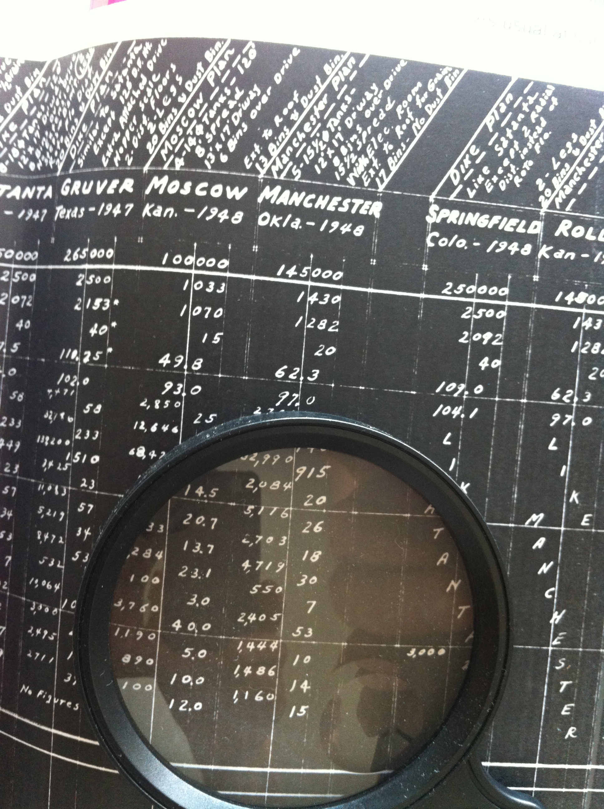
Once we arrived home, I had to resort to the company records to positively identify Tillotson Construction’s contribution to the site. The specifications for Ralston fit the size of the annex I had seen–a massive structure about twice the size of the average elevator project. Since this structure was an annex, many items normally included in a complete elevator build were not required. The Tillotson construction details are reproduced below.

The Ralston storage was built in 1953 using the “Ralston Plan,” which had eight 28′ diameter, 115′ tall bins with a 2′ spread, flat bottoms, and a screw conveyor.

Capacity per plans: 537,000 bushels

Capacity per foot of height: 4,838 bushels

Reinforced concrete per plans (total): 2,779 cubic yards

Plain concrete (4″ hoppers and liner): 9 cubic yards

Reinforcing steel per plans (includes jack rods): 168.18 tons

Average steel per cubic yard of reinforced concrete: 121.00 lbs.

Steel and reinforced concrete itemized per plans

Below main slab: steel 3,128 lbs.; concrete 29 cubic yards

Main slab: steel 102,340 lbs.; concrete 606 cubic yards

Draw form walls: steel 203,034 lbs.; concrete 1,920 cubic yards

Driveway and work floor: not installed

Deep bin bottoms: not installed

Overhead bin bottoms: steel 4,666 lbs.; concrete 24 cubic yards

Bin roofs and extension roofs: steel 14,284 lbs.; concrete 112 cubic yards

Cupola walls: steel 8,907 lbs.; concrete 20 cubic yards

Distributor floor: concrete 2 cubic yards (steel included in above total)

Cupola roof: concrete 3 cubic yards (steel included in above total)

Miscellaneous (boot, leg, head, track sink, steps, etc.): not installed

Attached driveway (in this plan, a gallery, with cross tunnel not included): concrete 63 cubic yards (steel included in above total)

DSC_6010Construction details

Main slab dimensions: 66 2/3′ x 121 2/3′

Main slab area (actual outside on ground): 7,738 square feet

Weight reinforced concrete (4,000 lbs. per cubic yard plus steel): 5,726 tons

Weight plain concrete (4,000 lbs. per cubic yard): 18 tons

Weight hopper fill sand (3,000 lbs. per cubic yard): 154 tons

Weight of grain (60 lbs. per bushel): 16,125 tons

Weight structural steel and machinery: 20 tons

Gross weight loaded: 22,043 tons

Bearing pressure: 2.86 tons per square foot

Main slab thickness: 24 inches

Main slab steel (size and spacing): straight; 1 1/4 square inches and 8 inches o. c.

Tank steel and bottom (round tanks): 5/8 inch diameter and 6 inches

Lineal feet of draw form walls and extension: 717 feet 7 inches; 39 feet 6 inches

Height of draw form walls: 115 feet

Pit depth below main slab: 9 feet 6 inches

Cupola dimensions (outside width and length and height): 12′ x 14′ x 20′

Pulley centers: 137 1/2 feet

Number of legs: 1 main (see pulley center above) and 1 jack

Distributor flow: yes

Track sink: no

Full basement: no

Electrical room: no.

Driveway width-clear: not installed

Dump grate-size: not installed

Columns under tanks: not installed

Boot–leg and head: steel

Machinery details

Head pulley (main leg): 48″ x 16″ x 4 15/16″

Boot pulley: 48″ x 13″ x 2 3/16″

RPM head pulley: 48 rpm

Belt: 15″-6 ply calumet

Cups: 14″ x 7″ at 10″

Head drive: Howell 40 horsepower: 3

Theoretical leg capacity (cup manufacturer’s rating): 7,950 bushels per hour

Actual leg capacity (80% of theoretical): 6,350 bushels per hour

Horsepower required for leg (based on above actual capacity): 26.4 horsepower

Man lift: not installed

Load out scale: not installed

Load out spout: not installed

Truck lift: not installed

Dust collector system: fan into bin

Cupola spouting: not installed

Driveway doors: not installed

Conveyor: 24 inch screws

Also built

Track scale: 50 foot, 50 ton: concrete 35 cubic yards


The Tillotson elevator in Lincoln, Nebraska is majestic in winter light

DSC_3138Story and photos by Kristen Cart

One of the most beautiful projects completed by Tillotson Construction of Omaha was their elevator with its annex in Lincoln, Neb. I was fortunate to be able to persuade my dad to stop with me to take some photos in perfect light.

DSC_3174One of the challenges of elevator photography is picking the structure out from its sometimes tight surroundings.

Usually you can take close pictures with a wide angle lens, which distorts straight lines, but can give you a full view of the elevator. In this case, I was without that tool since it broke when it fell off a chair, so I had to make do with a mid-range zoom lens.

You be the judge of whether the pictures were successful, given the limitations of distance, obstructions, and points of view.

DSC_3184

The trademark rounded headhouse rises above one of the largest elevators Tillotson Construction built

This elevator is a couple of blocks from the Cornhusker Highway in Lincoln, and one of the obstructions to a clear shot is an overpass feeding traffic to that main artery through town. The limited view required some cropping of the elevator. But the light and sky made up for the field of view.

The manhole covers display the company name on both the elevator and the annex

The manhole covers display the company name on both the elevator and the annex

We do not know why the Lincoln elevator is not among the projects recorded in the company ledgers. It appears that at least one page was missing from the records, and there is no way to know where it is, or why it is missing. So the only information we have about its construction is from the manhole cover on the main elevator, which says 1955. Presumably, the annex was built shortly thereafter.

Because the facility, AGP Grain Cooperative, was closed, we obtained no further details on this visit. This elevator will be the first on our list when the harvest time comes around again, and we can see the elevator in operation for ourselves.

Christmas ideas for an elevator enthusiast

DSC_0075Story and photo by Kristen Cart

Our good friend Linda Laird shares our interest in American grain elevators and has devoted much of her time to documenting these historic landmarks of the plains. I purchased her book some time ago and found it very enlightening. She did a terrific job. This book is on my short list of recommendations for Christmas, if you have an elevator lover on your list.

The American Grain Elevator

Another good friend and fine photographer Bruce Selyem, and his wife and excellent writer Barbara Selyem, have published several books on the subject of grain elevators, and they also publish an annual grain elevator calendar. Last time I checked they still had a few for sale. They also have fine prints for sale if you find an image of an elevator you can’t live without. I spend time on their site while planning elevator trips because of their extensive coverage of elevators all over the country and in Canada.

Grain Elevator Photos

Lastly, it is always a good idea to visit Gary Rich’s elevator photo pages to see his latest elevator photography. He recently finished a trip to Oklahoma, so I expect to see new images from there soon. He says he loves taking pictures in the winter sunshine, which is the perfect illumination for his subjects.

Gary Rich Grain Elevators

Enjoy the season!

The Tillotson elevator at Vail, Iowa, is fully explained in builder specifications

The ubiquitous curved headhouse exemplifies the Tillotson style at Vail, Iowa

The curved headhouse exemplifies the Tillotson style at Vail, Iowa.

Story and photos by Kristen Cart

DSC_2984

An overexposed image brought out the Tillotson name on the blue port cover.

During our travels, we are always on the lookout for a Tillotson elevator, so coming across the Vail elevator in the eastern part of Iowa during a Thanksgiving visit was a pleasant surprise.

The trademark curved headhouse came into sight at a distance, and with some excitement we pulled over near the elevator, hoping to find an embossed manhole cover to confirm the builder. Painted blue, about halfway up the side above a loading spout, was a steel cover with its stamped name, “Tillotson Construction Co., 1955, Omaha Nebr.,” faintly visible in the late afternoon shadow.

We needn’t have looked. The Vail elevator is among the structures detailed in the Tillotson concrete elevator specifications, which span over fifteen years.

In a brisk, chill wind, I took some quick photographs (interrupted briefly when a railroad employee warned me to keep a respectful distance from the tracks), and then I dashed back into the warmth of the truck. “Vail, Iowa,” was a familiar name. When I checked, I found it was listed in the rich store of information that Tim Tillotson provided.

Eureka!

DSC_3006Below are the specifications for the elevator at Vail, Iowa, built in 1955.

The elevator was built using the “Manson plan,” which specified 5 bins with a 16 ft diameter and 120 ft height, a 13 x 17 ft driveway, a dust bin and fan, a dryer bin, and 16 bins and overflow.

Capacity per Plans (with Pack) 152,000 bushels

Capacity per foot of height 1,551 bushels

Reinforced concrete/plans (Total) 1,552 cubic yards

Plain concrete (hoppers) 27 cubic yards

Reinforced steel/Plans (includes jack rods) 69.5 tons

Average steel per cubic yard of reinforced concrete 89.8 pounds


Steel & reinforced concrete itemized per plans

Below main slab 5,457 lb/64 cu yd

Main slab 19,460 lb/186 cu yd

Drawform walls 88,017 lb/1087 cu yd

Work & driveway floor (including columns) 1,988 lb/18.5 cu yd

Deep bin bottoms 5,261 lb/28.5 cu yd

Overhead bin bottoms 2,949 lb/22.1 cu yd

Bin roof & Extens. roofs 5,287 lb/35.8 cu yd

Scale floor (complete) 292 lb/4.8 cu yd

Cupola walls (including leg and head) 5,590 lb/63.0 cu yd

Distributor floor 1,530 lb/11.0 cu yd

Cupola roof 1,760 lb/14.0 cu yd

Miscellaneous (track sink, steps) 1,107 lb/15.0 cu yd

Construction details

Main slab dimensions (Drive length first dimen.) 54 x 51 ft

Main slab area (actual outside on ground, less pit) 2,482 sq ft

Weight of reinforced (total) concrete (4,000 lb/cu yd + steel) 3,173 tons

Weight of plan concrete (hoppers 4,000 lb/cu yd) 96 tons

Weight hopper fill sand (3,000 lb/cu yd) 615 tons

Weight of grain (at 60 lb per bushel) 4,560 tons

Weight of structural steel & machinery 18 tons

Gross weight loaded 8,462 tons

Bearing pressure 3.4 tons per sq ft

Main slab thickness 24 in

Main slab steel (bent) number 9 at 7 inches

Tank steel at bottom (round tanks) number 4 at 12 inches

Lineal feet of drawform walls and extensions 526 ft

Height of drawform walls 120 ft

Pit depth below main slab 16 ft 3 in

Cupola dimensions (W x L x Ht.) 22.25 x 42.5 x 26.5 ft

Pulley centers 152.75 ft

Number of legs 1

Distributor floor Yes

Track sink Yes

Full basement Yes

Electrical room Yes

Driveway width–clear 13 ft

Dump grate size 5 x 9 and 15 x 9 ft

Columns under tanks size 16 inches square

Boot — leg & head Concrete


Machinery Details

Head pulley size 72 x 14 x 4 9/16 in

Boot pulley size 72 x 14 in

Head pulley rpm 42

Belt 330 ft, 14 in 6 ply calumet

Cups 12 x 6 in at 10 1/2 in

Head drive Howell 30 horsepower, 4

Theoretical leg capacity (cup manufacturer rating) 6,440 bushels per hour

Actual leg capacity (80 percent of theoretical) 5,150 bushels per hour

Horsepower required for leg (based on above actual capacity plus 15 percent for motor) 23.8 hp

Man lift 1.5 horsepower Ehr

Load out scale 10 bu

Load out spout 8.25 inch W.C.

Truck lift 7.5 horsepower Ehr

Dust collector system Fan → Bin

Cupola spouting 10 inch diam.

Driveway doors Two overhead rolling

Conveyor Provision


Also Built

Main slab includes 3 in pile cap 23 cu yd

Split one overhead bin

Dust bin and fan

Hang pit 3,126

Special track sink

Piling

A chance encounter with a Tillotson elevator in Jamestown, Kansas

DSC_0057

Sporting a fresh coat of paint, the trademark Tillotson elevator with its curved headhouse still operates. 

Story and photos by Kristen Cart

On our last elevator road trip, which our family embarked upon in October 2012, we visited many of our grandfathers’ elevator projects from the 1940s and 50s. But we also amassed a photo collection of elevators we could not place. Either the grain cooperatives were closed for business on a Sunday, or the elevators were retired, or we didn’t have time to stop for an interview. So the photos languished for most of a year, until Ronald Ahrens and I could identify them, even though we strongly suspected that the structures were the works of one of our grandfathers.

One of the mystery elevators was a pure white example, located in the north-central Kansas town of Jamestown. Ronald’s uncle, Tim Tillotson, recently handed us the Omaha builder’s construction specifications, which finally identified this handsome elevator as a project built in 1953 by the Tillotson Construction Company.

A smaller elevator stands on a branch of the rail line. It's builder is unknown.

A smaller elevator stands on a branch of the rail line. It’s builder is unknown.

The Jamestown elevator stands not far from a companion elevator, rising alone on a fork of the railroad track. The smaller elevator was built in a straight-up style that predates the more common Tillotson style, and it’s provenance is unknown. It is reminiscent of the style of the elevator built by Tillotson Construction in Greenwood, Neb., but without the curved headhouse. But it also recalls several Chalmers and Borton examples.

It is our good fortune to have the detailed specifications for the Jamestown elevator. Thanks to the Tillotson Company’s meticulous record keeping and the decades-long survival of the records, we can share the construction details of this remarkable structure. The specifications, for the engineering-minded among our readers, are presented below.

Capacity per Plans (with Pack) 155,320 bushels

Capacity per foot of height 1581 bushels

Reinforced concrete/plans (Total) 1530 cubic yards

Plain concrete (hoppers & liner) 17 cubic yards

Reinforced steel/Plans (includes jack rods) 69.38 tons

Average steel per cubic yard of reinforced concrete 90.6 pounds


Steel & reinforced concrete itemized per plans

Below main slab 4260 lb/52 cu yd

Main slab 19,427 lb/160 cu yd

Drawform walls 89,400 lb/1107 cu yd

Work & driveway floor (including columns) 1997 lb/18.5 cu yd

Deep bin bottoms 5236 lb/28.5 cu yd

Overhead bin bottoms 3175 lb/24 cu yd

Bin roof & extended roofs (or corner) 5139 lb/37.4 cu yd

Scale floor (complete) 292 lb/4.8 cu yd

Cupola walls 4897 lb/52.5 cu yd

Distributor floor 1530 lb/11 cu yd

Cupola roof 2207 lb/14 cu yd

Miscellaneous (boot, leg, head, track sink, steps, etc.) 1205 lb/20.3 cu yd (excluding track scale)

(At the head of the column on the next page, the Jamestown elevator was described thus: “Clifton Imo plan; Like Meno but split dust bin for Bin #17”)


Construction details

Main slab dimensions (Drive length first dimen.) 54 x 51 feet

Main slab area (actual outside on ground) 2625 square feet

Weight of reinforced (total) concrete (4000#/cu yd + steel) 3130 tons

Weight of plain concrete (4000#/cu yd) 34 tons

Weight hopper fill sand (3000#/cu yd) 684 tons

Weight of grain (at 60# per bushel) 4660 tons

Weight of structural steel & machinery 18 tons

Gross weight loaded 8526 tons

Bearing pressure 3.25 tons per sq ft

Main slab thickness 21 inches

Main slab steel (bent) 1 in diameter at 7 inch o.c.

Tank steel at bottom (round tanks) 0.5 inch diameter at 12 inch o.c.

Lineal feet of drawform walls 514 feet including exterior

Height of drawform walls 120 feet

Pit depth below main slab 15 feet 9 inches

Cupola dimensions (outside W x L x Ht.) 22.25 x 42.5 x 26 feet

Pulley centers 152.66 feet

Number of legs 1

Distributor floor Yes

Track sink Yes

Full basement Yes

Electrical room Yes

Driveway width–clear 13 feet

Dump grate size 2 @ 9 feet wide

Columns under tanks size 16 inches square

Boot — leg & head Concrete

(The remaining specs were noted “same as Meno.” The Meno specifications are given below.)

Machinery Details

Head pulley 72 x 14 x 4 7/16 inches

Boot pulley 72 x 14 x 2 3/16 inches

R.P.M. head pulley 42 rpm

Belt 14 inch 6 ply Calumet

Cups 12 x 6 inch at 9 inch o.c. Howell

Head drive 40 horsepower

Theoretical leg capacity (cup manufacturer rating) 7500 bushels per hour

Actual leg capacity (80 percent of theoretical) 6000 bushels per hour

Horsepower required for leg (based on above actual capacity plus 15 percent for motor) 27.75 hp

Man lift 1.5 horsepower Ehr

Load out scale 10 bushel Rich

Load out spout 10 inch W.C.

Truck lift 7.5 horsepower Ehr.

Cupola spouting 8.25 inch W.C.

Truck lift 7.5 horsepower Ehr

Dust collector system Fan → Bin

Cupola Spouting 10 inch W.C.

Driveway doors Two overhead rolling

Conveyor Not required

(Items below were listed for Meno; it is not clear whether these were also built at Jamestown)


Also Built

60 foot 50 ton scale: 40 cu yd

2 sk’ing spts (scaffolding supports?)

Full specifications of Tillotson Construction’s elevator in Moscow, Kansas

The construction record was written with painstaking attention to detail.

The construction record was written with painstaking attention to detail.

Our friend Linda Laird has asked if the Tillotson Construction Company’s records included any Kansas elevators. The answer is yes, and here’s an example.

In 1948, Tillotson built an elevator of reinforced concrete at Moscow, in the extreme southwestern corner of the Sunflower State. The plan’s basic aspects were as follows: four tanks of 14 feet in diameter, 120 feet in height, and an eight-foot spread. The driveway was was 13 x 17 feet and there were six bins over the drive. Another notation says “Ext. to roof.” This shows up on most other plans and is supplemented by “1/2 grain” or “for grain.” The final item at the head of the plan’s entry in company records notes “13 bins & dust bin.”  Here are all the data:

Capacity per Plans (with Pack) 100,000 bushels

Capacity per foot of height 1033 bushels

Reinforced concrete/plans (Total) 1070 cubic yards

Plain concrete (hoppers) 15 cubic yards

Reinforced steel/Plans (includes jack rods) 49.8 tons

Average steel per cubic yard of reinforced concrete 93.0 pounds


Steel & reinforced concrete itemized per plans

Below main slab 2850 lb/25 cu yd

Main slab 12,646 lb/91 cu yd

Drawform walls 68,424 lb/812 cu yd

Work & driveway floor (including columns) 1790 lb/14.5 cu yd

Deep bin bottoms 3740 lb/20.7 cu yd

Overhead bin bottoms 1733 lb/13.7 cu yd

Bin roof (corner) 2284 lb/23.1 cu yd

Scale floor (complete) 100 lb/3.0 cu yd

Cupola walls 3750 lb/40.0 cu yd

Distributor floor 1190 lb/5.0 cu yd

Cupola roof 890 lb/10.0 cu yd

Miscellaneous (boot, leg, head, track sink, steps) 100 lb/12.0 cu yd

Construction details 

Tillotson's Moscow, Kan., elevator, right, was built in 1948. The annex had to come later. Photo by Kristen Cart.

Tillotson’s Moscow, Kan., elevator, right, was built in 1948. The annex had to come later. Photo by Gary Rich.

Main slab dimensions (Drive length first dimen.) 40 x 45 feet

Main slab area (actual outside on ground) 1712 sqare feet

Weight of reinforced (total) concrete (4000#/cu yd + steel) 2190 tons

Weight of plan concrete (hoppers 4000#/cu yd) 30 tons

Weight hopper fill sand (3000#/cu yd) 260 tons

Weight of grain (at 60# per bushel) 3000 tons

Weight of structural steel & machinery 10 tons

Gross weight loaded 5490 tons

Bearing pressure 3.21 tons per sq ft

Main slab thickness 18 inches

Main slab steel (straight) 1 in diameter at 6 inch o.c.

Tank steel at bottom (round tanks) ⅜ inch diameter at 9 inch o.c.

Lineal feet of drawform walls 382 feet including exterior

Height of drawform walls 120 feet

Pit depth below main slab 11 feet 0 inches

Cupola dimensions (W x L x Ht.) 14 x 36 x 23 feet

Pulley centers 145.5 feet

Number of legs 1

Distributor floor Yes

Track sink Yes

Full basement Yes

Electrical room Yes

Driveway width–clear 12 feet

Dump grate size 2 – 6 x 11 feet

Columns under tanks size 20 inches square

Boot — leg & head Concrete


Machinery Details

Looking down the crowded streets of Moscow at Tillotson's elevator, far right. Photo by Kristen Cart.

Looking down the crowded streets of Moscow at Tillotson’s elevator, far right. Photo by Gary Rich.

Boot pulley 60 x 14 x 2 3/16 inches

Head pulley 60 x 14 x 3 15/16 inches

R.P.M. head pulley 42 rpm

Belt 14 inch 6 ply Calumet

Cups 12 x 6 inch at 8.5 inch o.c. Howell

Head drive 30 horsepower

Theoretical leg capacity (cup manufacturer rating) 66.0 bushels per hour

Actual leg capacity (80 percent of theoretical) 52.8 bushels per hour

Horsepower required for leg (based on above actual capacity plus 15 percent for motor) 23.3 hp

Man lift 2 horsepower Ehr

Load out scale Two 10 bushel Rich

Load out spout 8.25 inch W.C.

Cupola spouting 8.25 inch W.C.

Truck lift 7.5 horsepower Ehr

Dust collector system Fan → Air

Driveway doors Two overhead rolling

Conveyor Not required


Also Built

Office

Truck scale 45 x 10 feet — 50 ton

J. H. Tillotson, Contractor, built their elevator scale houses with distinctive flair

The scale house at Monument, Kan., above, is almost identical to the one at Lodgepole, Neb.

The details of the scale house at Monument, Kan., above, are almost identical to those at Lodgepole, Neb. Photo by Kristen Cart

Story by Kristen Cart

Elevator construction was driven by stringent engineering requirements, lending a degree of commonality to the buildings. A few distinguishing details could be noticed, but from a distance you would be hard pressed to determine the builder. When contractors built the accompanying buildings, however, they had free reign to build in a style they could call their own. Often the scale houses would be instantly recognizable.

Lodgepole, Neb.

Lodgepole, Neb. Photo by Kristen Cart

J. H. Tillotson’s designs lent themselves well to the addition of a stylish scale house built alongside the main elevator. In some cases, when visiting an elevator, our access was limited. Then the lines of the scale house would be the only clue that we were looking at a J. H. Tillotson elevator.

Below are a few examples, each adapted to its individual setting, but each showing some distinguishing details that were common to all. Each J. H. Tillotson scale house was built of concrete, with a rectilinear floor plan. Usually they incorporated a protruding bay window, on the side facing the scale, for added visibility. Stairs, usually with steel railings, led to a door to accommodate truckers’ entry into the building. Carefully executed details in the concrete expressed the architect’s personal sense of style.

The scale house at the now demolished elevator at McAllister, Kan., is the only clue we have to its builder. Photo by Gary Rich

The scale house at the now demolished elevator at McAllaster, Kan., is a clue to its builder. Photo by Gary Rich

The scale house at Bradshaw, Neb. sports new siding over its concrete walls. Photo by Kristen Cart

The scale house at Bradshaw, Neb., sports new siding over its concrete walls. Photo by Kristen Cart

The scale-house at the Farmers Co-op, Daykin, Neb. shows characteristic corner details. Photo by Kristen Cart

The scale house at the Farmers Co-op, Daykin, Neb., shows characteristic corner details. Photo by Kristen Cart

While the builder of the elevators at McAllaster and Bradshaw has not been established with certainty, a fair case can be made that they were J. H. Tillotson designs based on details of the elevators themselves, the driveways, and the scale houses, when compared with known elevators. The scale house at Daykin, Neb., is included here for comparison.

J. H. Tillotson’s designs were visually appealing, with scale houses that contributed to a harmonious whole. When considering a builder, buyers would judge the quality of the elevator by its beauty, among other things. In this regard, J. H. Tillotson, Contractor, was more successful than most.

Scale houses express graceful utility, epitomize contemporary style

Daykin, Neb. scale house built by J. H. Tillotson, Contractor

Daykin, Neb., scale house built by J. H. Tillotson, Contractor.

Story and photos by Kristen Cart

An often unnoticed feature of every grain elevator is the scale house. The scale house is home to the cooperative site office, and is the place where the elevator conducts its primary business. It is usually an unassuming building where empty grain trucks pull up to be weighed before filling up. The trucks make a second visit when laden with grain, and the difference in weight is tallied in the office. Conversely, when a full grain truck pulls up to deposit its grain, it must return after unloading to determine how much has been loaded into the elevator. Inside the scale house, a small sample of the grain is tested for quality and moisture content.

The scale house in Benton, Kan.

The scale house in Benton, Kan.

Many scale houses are metal or brick buildings, often unattached to the elevator and some distance away. Most are  unremarkable. But some of the old concrete scale houses have unique charm. The scale houses that accompanied J. H. Tillotson elevators were particularly attractive, and are one of the first things to look for when identifying their elevators.

Scale house in Willows, Calif.

Scale house in Willows, Calif.

DSC_0538

Other builders also produced some remarkable scale houses. Elevator building was driven by engineering and economical constraints, but in some cases the scale houses received special attention. In Willows, Calif., I photographed an example that had to take first prize. This dandy building recalls a 1960s drive-in burger joint, complete with car-side speakers and root beer floats. While it is not an example of our grandfathers’ work, it deserves notice.

The simple lines of the back of the scale house at Kanorado, Kan.

The simple lines of the back of the scale house at Kanorado, Kan.

Joseph H. Tillotson developed a characteristic style for the scale houses his company built. Those I have visited appeared to be concrete, and many had attractive details. For more typical examples of his work, stay tuned.

A photo tour at Kanorado, Kansas, reveals subtle J. H. Tillotson design details

DSC_0642Story and photos by Kristen Cart

One of the best stops on my elevator tour last October was Kanorado, Kan. It was a fortuitous visit, made in the golden hour of photographic light. We have profiled the elevator before, based upon a visit by Gary Rich while the elevator was operating and open for an impromptu tour. But I wanted to see for myself the elevator my grandfather William Osborn built.

No one was there when we arrived, but I was able to get a good look at all sides of the structure. The straight up, classic lines were unique to  J. H. Tillotson elevators.

DSC_0664

A view of the integral headhouse with windows to admit light

Other companies built similarly styled elevators, such as the Greenwood, Neb. elevator built by Tillotson of Omaha in 1951. But those differed in shape and concrete detailing. The elevator at Kanorado was an earlier effort, and should be compared with those at Traer, Kan., Goodland, Kan., and Wauneta, Neb., among others.

DSC_0655

Late afternoon shadows are cast across the drive-through scale


Another design element that seems to be unique to Joseph H. Tillotson’s Denver-based company is the squat concrete scale house, a deceptively simple building with lovely proportions, as can also be seen with the J. H. Tillotson elevator at Daykin, Neb.

DSC_0687It is good to see another 1940s vintage elevator still doing its job nearly 70 years later. It is a testament to a work ethic that seems quaint in our present day, and a personal investment in quality beyond the next payday. My grandfather would be proud.

A photography outing reveals beauty at the Mayer-Osborn elevator in Byers, Colorado

DSC_0221

A documentary photograph of the Byers, Colo. elevator.

In the fall of 2012, Gary Rich, contributor to this blog, treated me to a photo tour of western Colorado elevators. I made a special stop to meet Gary and his wife Sandy. The last few years Gary has specialized in elevator photography, capturing the beauty and spare elegance of grain elevators, identifying their builders as he went. The Byers, Colo., elevator is one of the loveliest.

DSC_0212

Gary Rich, camera in hand, looks for a better shot.

Sandy Rich is a very good photographer in her own right, and she has challenged Gary to greater creativity in his compositions.  He explained how her inspiration led him away from “documentary” shots and toward more artistic photography. When we stopped at Byers, Colo., we took some of her ideas to heart, and we were very pleased with the results.

Mayer-Osborn construction built the Byers elevator in 1950, as noted in a contemporary newspaper account. My father Jerry Osborn remembers his dad William Osborn working on it.

DSC_0205

Using the foreground to frame the subject adds interest to the photograph. Gary shot this composition first as can be seen on his photo site.

Retaining some of the characteristics of the earlier J. H. Tillotson elevators, the Byers elevator recalls those at Traer and Hanover, Kan. The Byers elevator is bigger than the Hanover elevator, and you can see where design adjustments accommodate the greater volume. The windows are very similar to those at Traer. The manhole covers on the exterior at Byers represent an innovation to fulfill local needs.

Since elevator designs continued to improve over time, an elevator design genealogy becomes apparent. The innovations cross company boundaries and are seen by looking at elevators chronologically, especially where the same builders and architects continued working in the business, bringing their ideas to one company after another. This is a chronology we are still trying to understand.

As we strive to understand elevator history, we take pictures. Elevators are worthy of our understanding and preservation for their beauty, not just their utility. Beautiful photos convey that message in a way that words can never express.

DSC_0241

The manhole covers on the exterior of the Byers elevator identify Mayer-Osborn as the builder.

DSC_0227