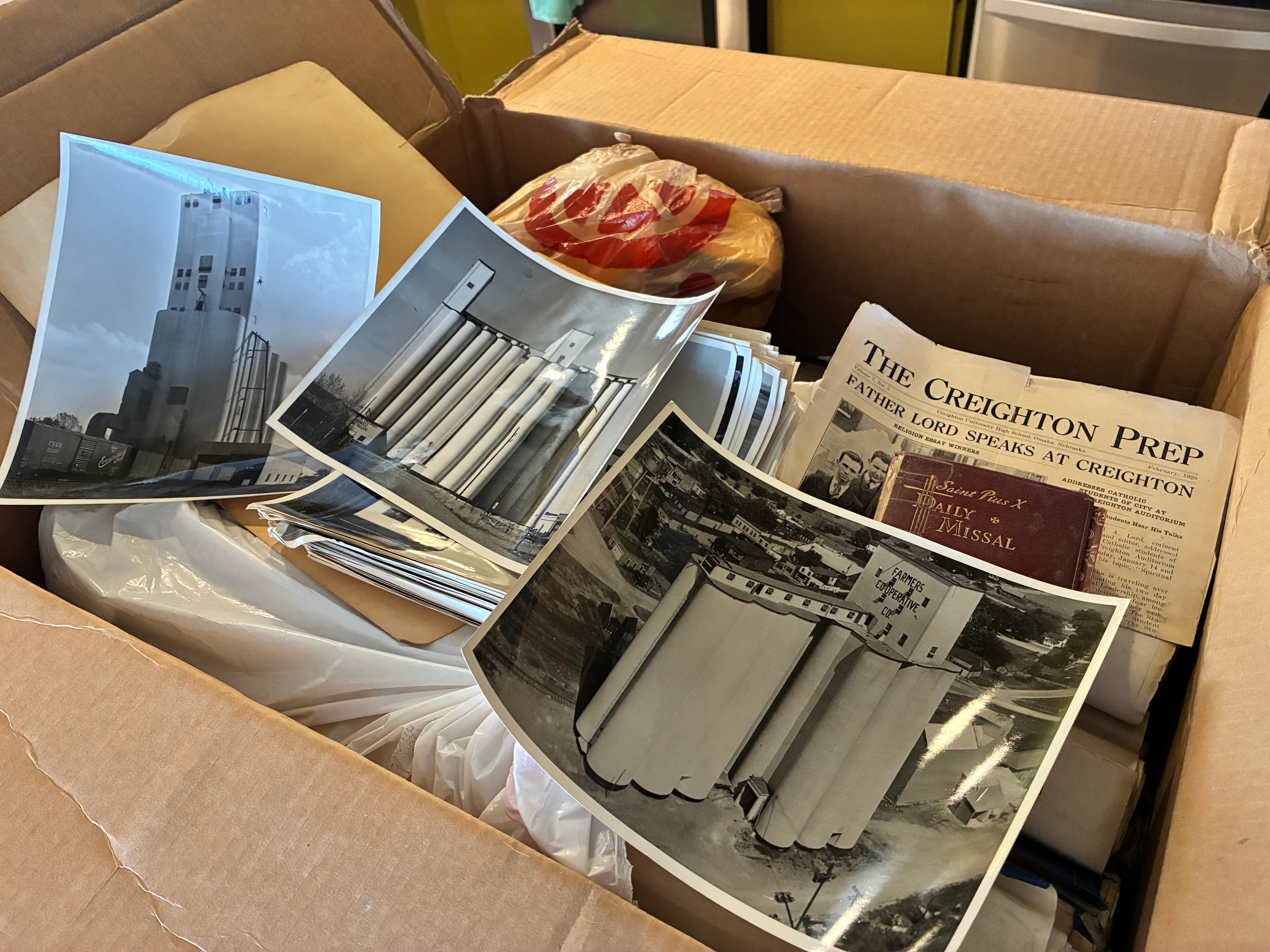
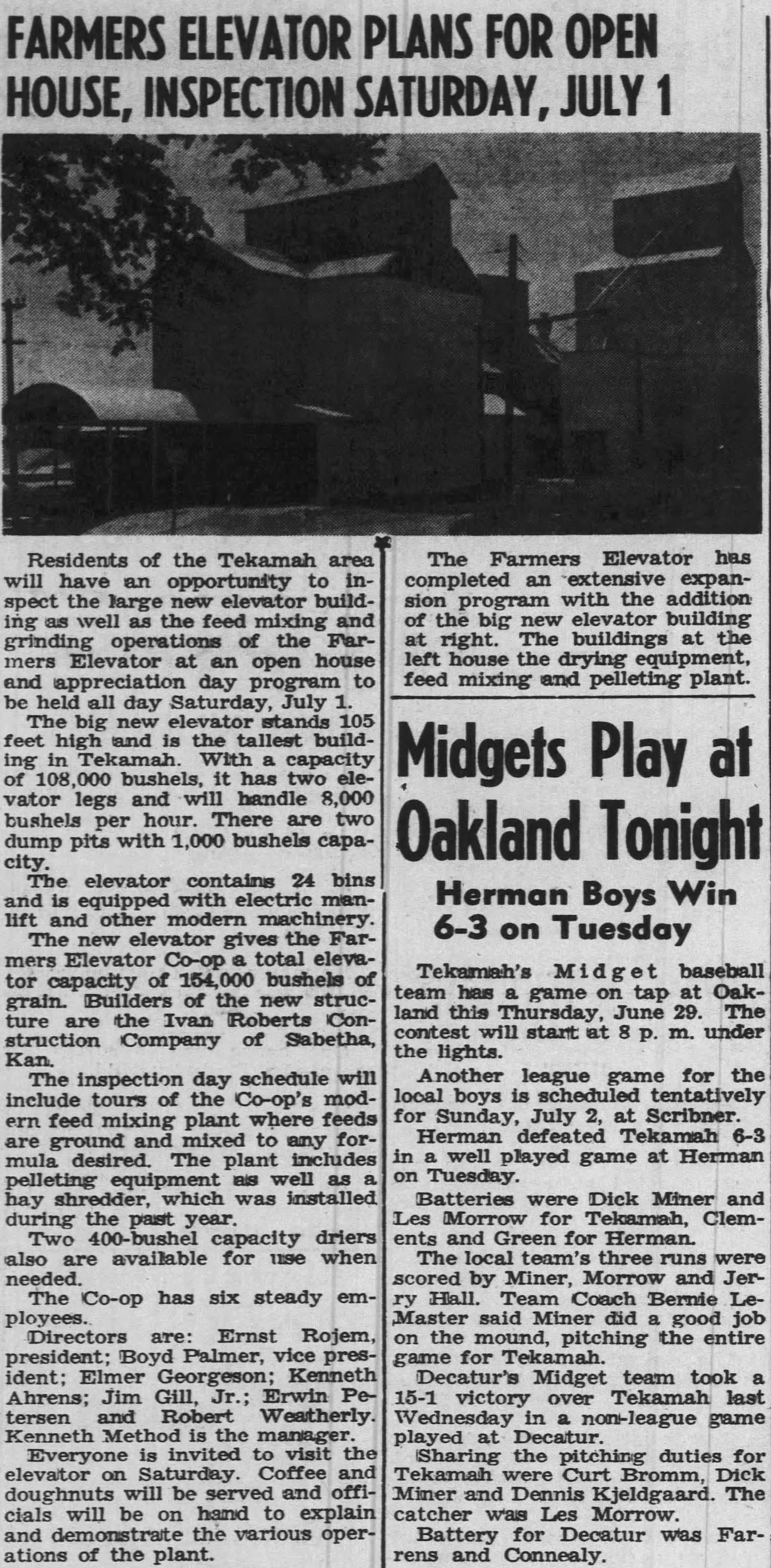
This much is known: Tillotson Construction Co. performed a job for E.M. Peet Manufacturing Co. in Council Bluffs, Iowa. It’s with apparent disinterest, or at best indifference, that the backs of two photos are marked “Warehouse.” No record of the job itself can be located, so we have to guess the date and what exactly was built. A 5,000-square-foot addition was done in 1958 to increase sacking and storage capacity as Peet’s joined the trend of adding bulk-storage bins, six in all. But that small job went to Ranch Construction Co., with Grain Storage and Construction Co. getting the machinery contract.
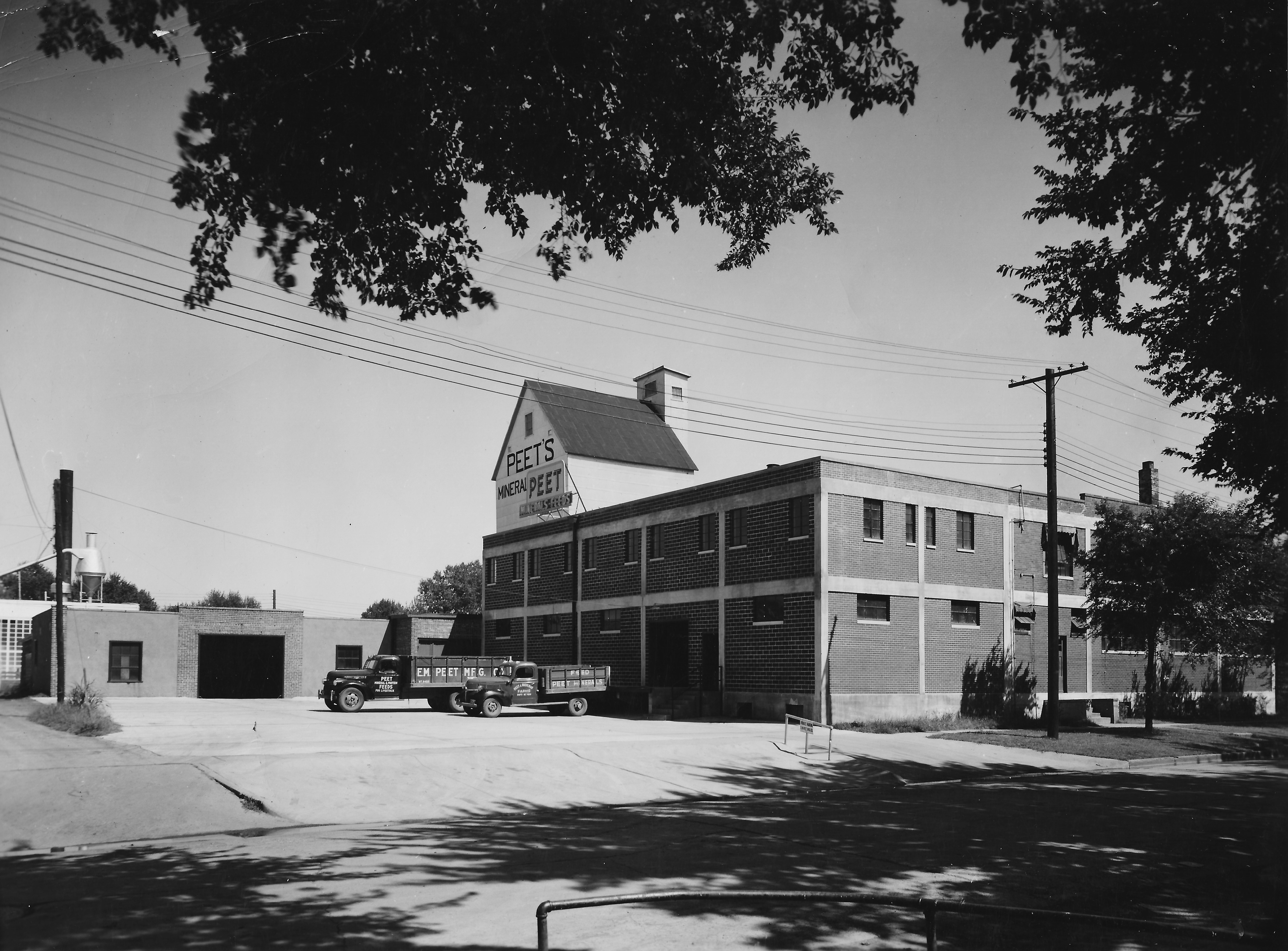
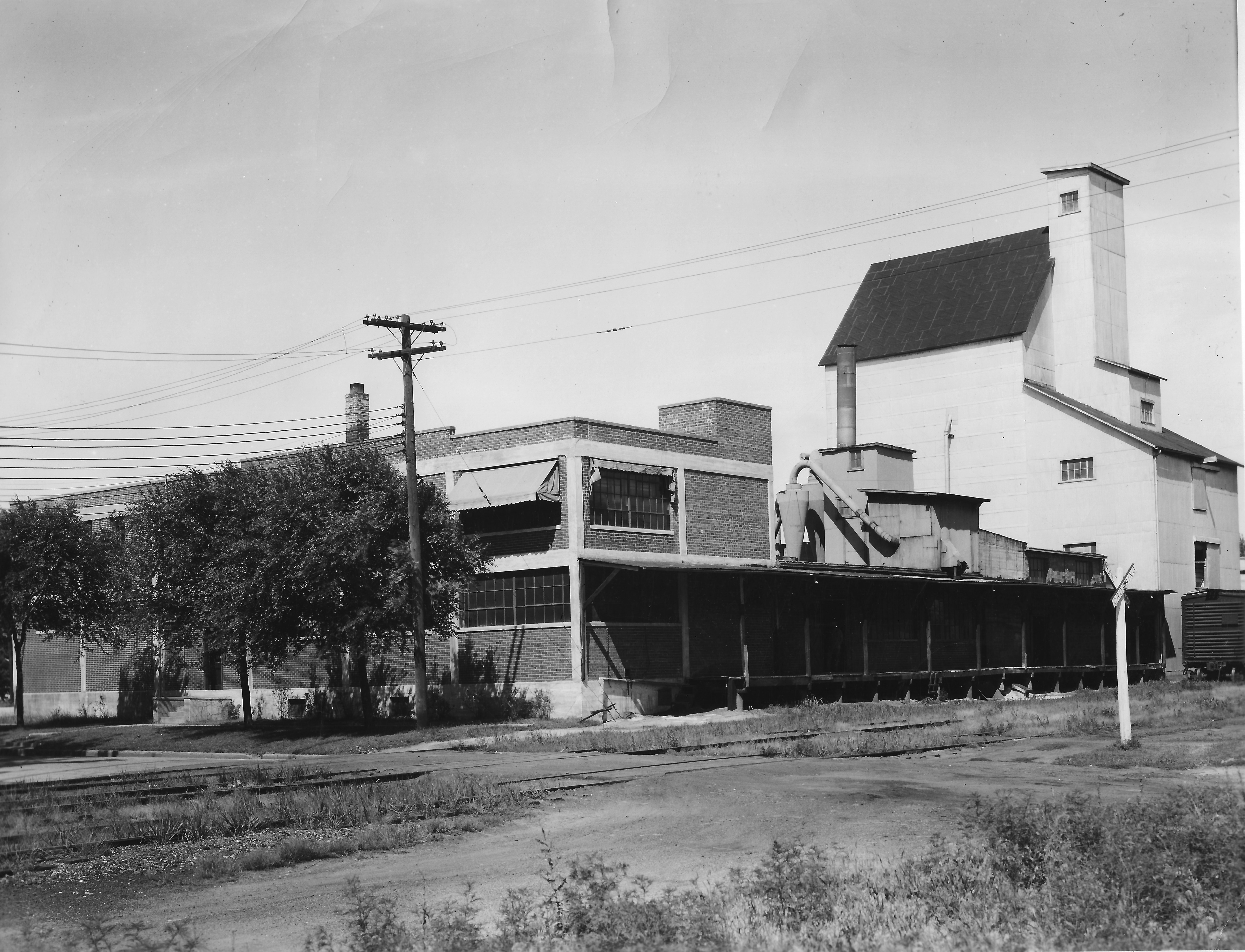
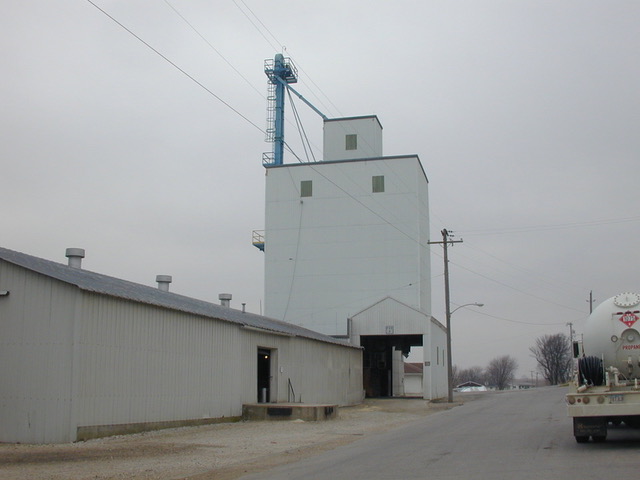
The photos suggest Tillotson Construction did a bigger project. We estimate the width of the two-story building at 80 feet. Could 15,000 square feet be too high for the total volume?
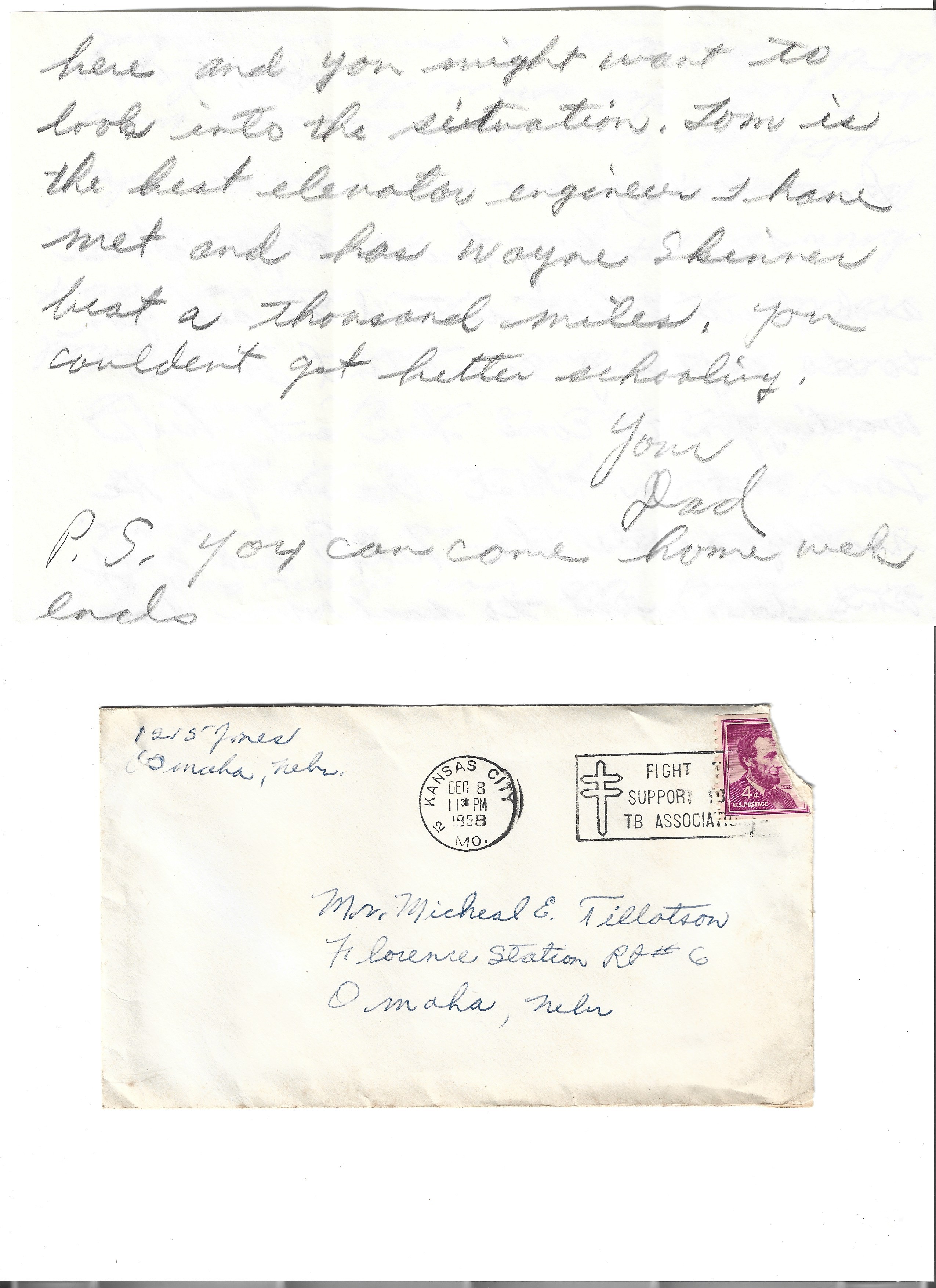
We’re trying to identify the two trucks and their model years, which could be pre-World War Two.
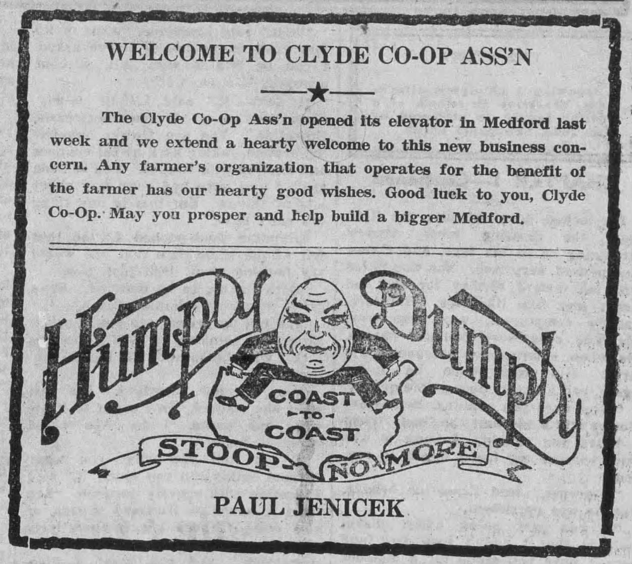
The next best clue for the date of Tillotson’s job is a Peet’s newspaper ad.
E.M. Peet Manufacturing Co. was founded in 1917 by Ernest M. Peet and W.A. Ruehlman. It was Peet who ran the company as president, making livestock and poultry feeds. Besides their home location at 33 S. 25th St., Peet’s had branches in several states. They also had test farms.
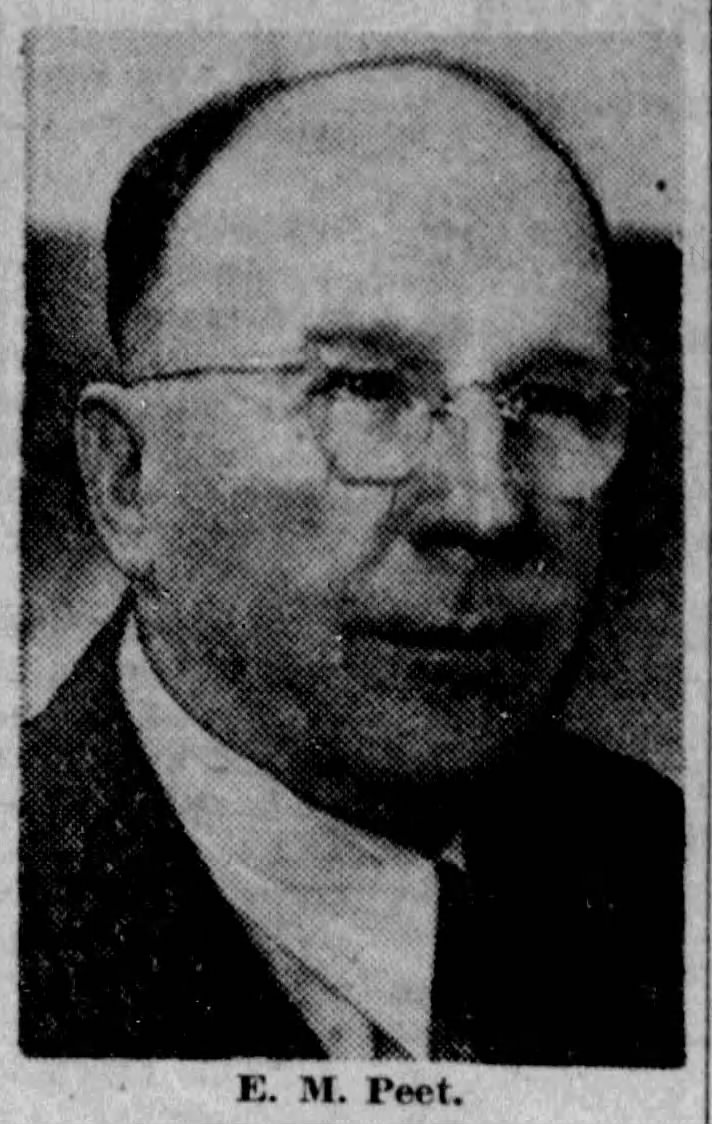
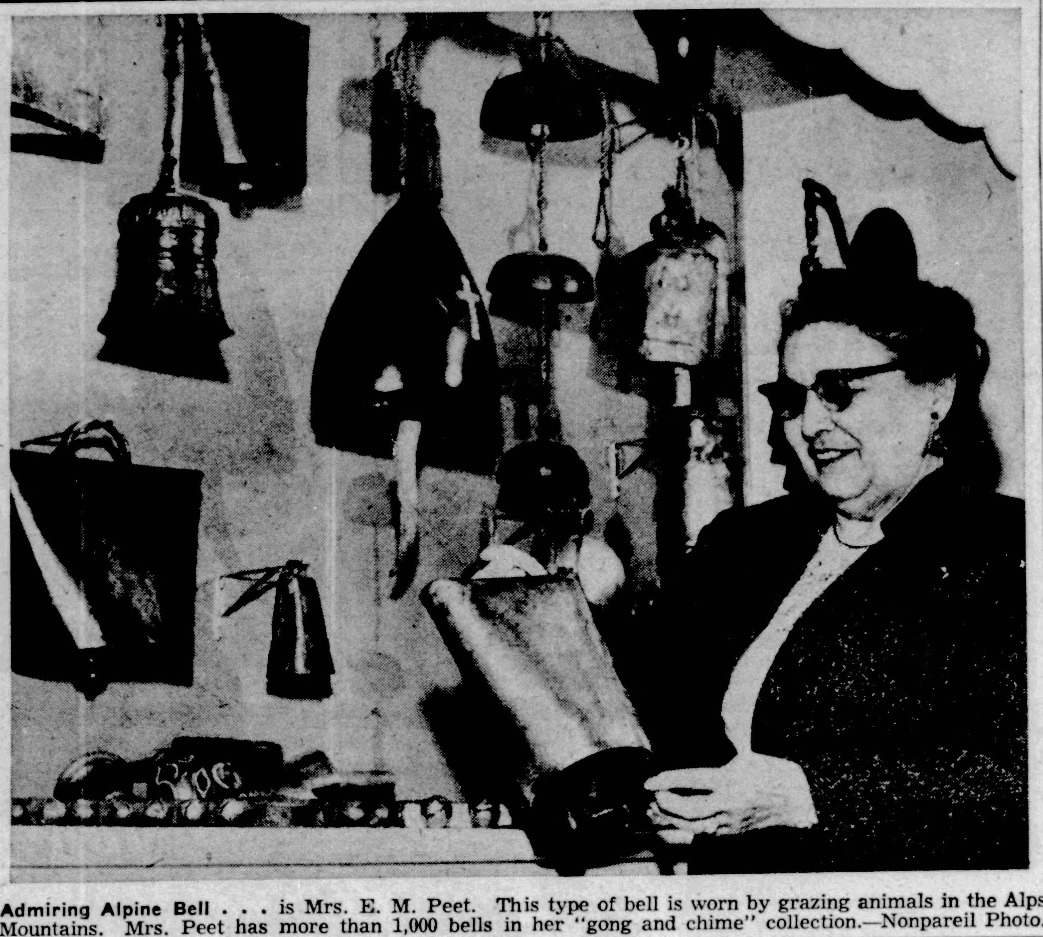
Pete was a Christian Scientist and belonged to fraternal lodges in the Bluffs. He and his wife Ethel lived at 163 Glen Avenue. Their daughter was Mrs. Dorothy Bammann. Ethel proved to be a ding-a-ling. She belonged to the American Bell Association and collected more than 1,000 bells. She used to drag out her suitcase and pack her dress, the one with bells sewn on it, and go to the ABA’s annual conventions in different cities.
“Everybody comes dressed with bell accessories in some manner,” she told the Daily Nonpareil’s “What’s Your Hobby?” column.
Ernie Peet was 63 years old when he died Dec. 10, 1944—a shock to the community. More than 500 people including 75 of his salesmen attended the funeral, and there were truckloads of flowers. The Daily Nonpareil lamented:
The death of E.M. Peet has left Council Bluffs without one of its best established and well-known business leaders. His loss will be felt for a long time.”
The revealing newspaper ad we referred to ran on February 11, 1945.
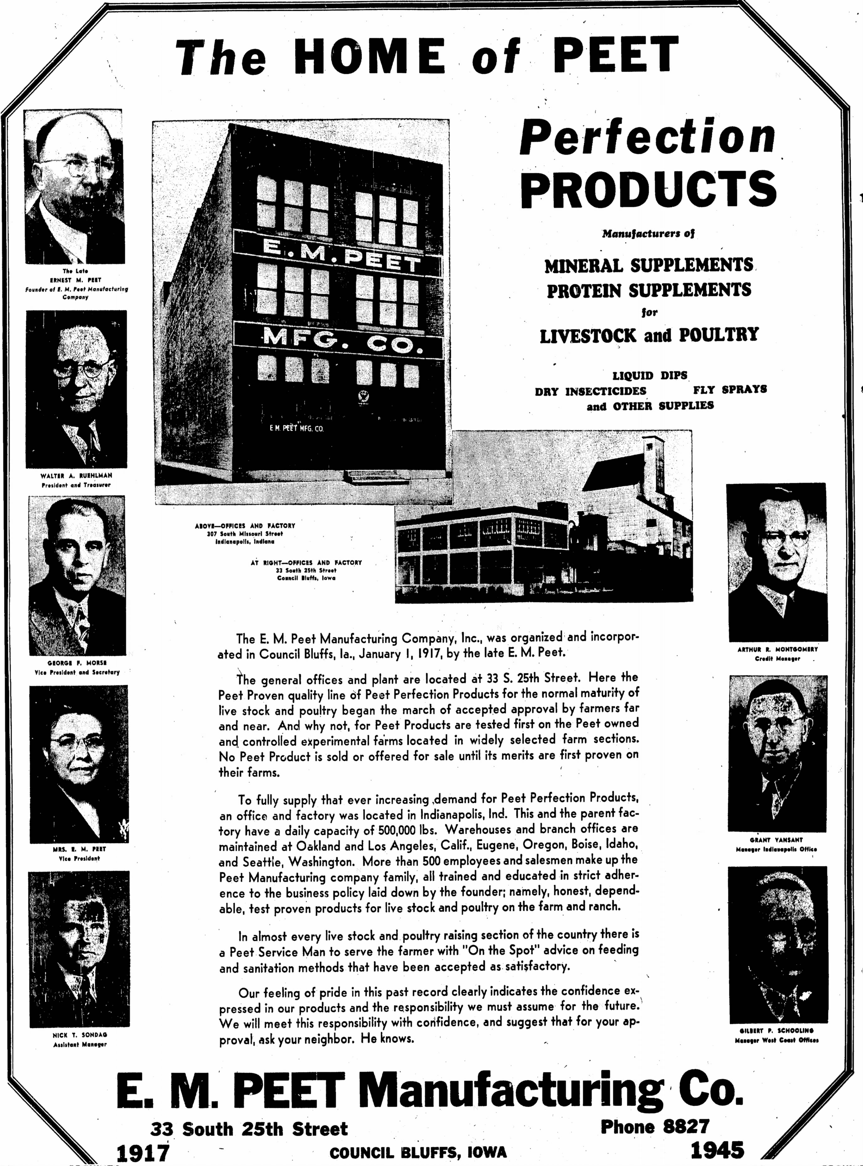
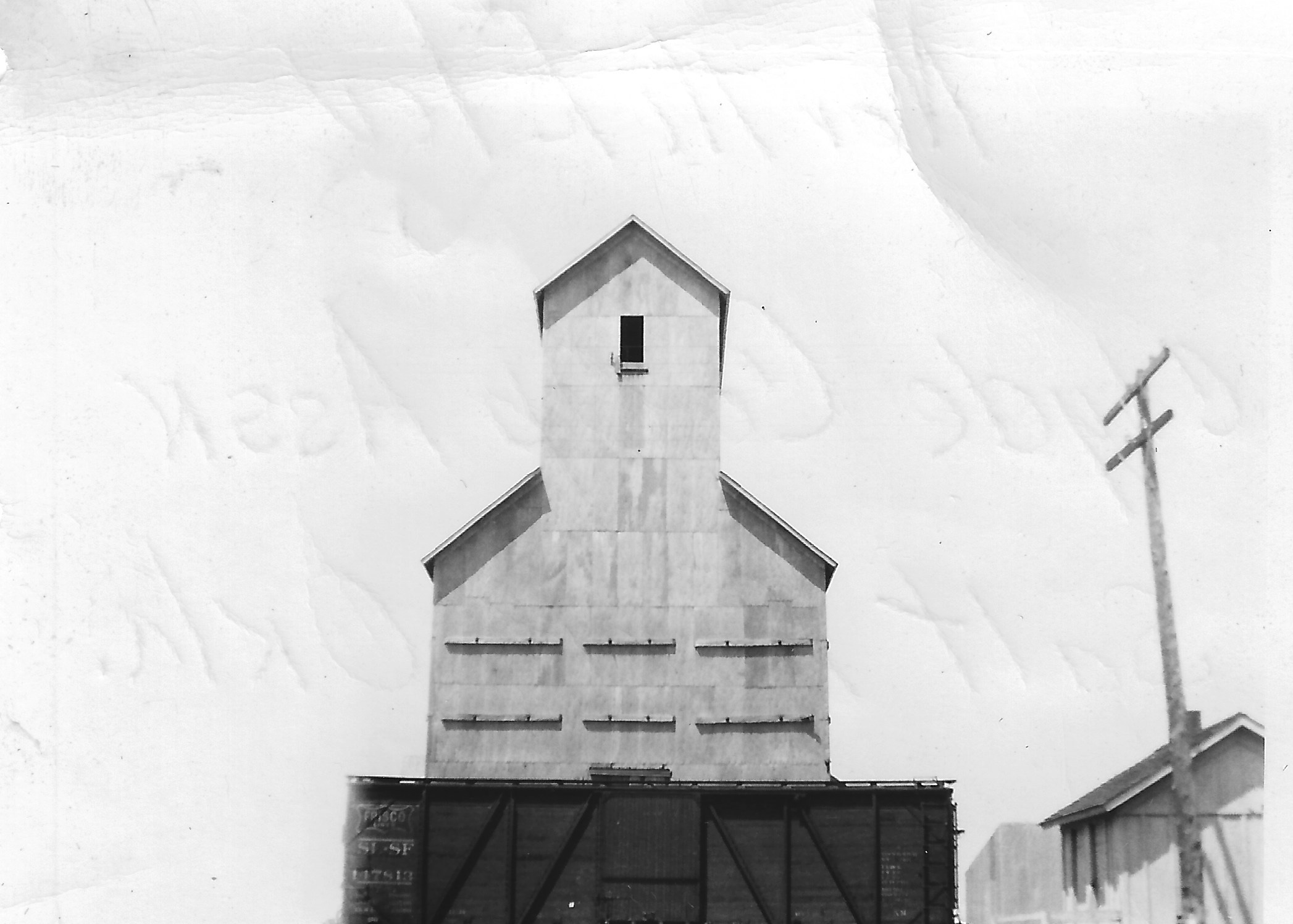
Until Reginald Tillotson speaks from his own grave, we have no way of pinning down whether the warehouse was done in Peet’s lifetime, but it’s interesting that the archival photo (top of post) matches the photo of Peet’s operation in the ad. All this indicates an early job for Tillotson Construction, one they finished well before Ernie Peet’s death.
Peet’s was big enough that its sales staff would congregate for special presentations on the latest advances. In 1951, for example, a group of 75 convened for three days at the Hotel Chieftain and, among other things, heard a University of Minnesota professor report new measures in animal nutrition such as adding Vitamin B-12, select minerals, and even antibiotics to the feed.
All that was for bovine and porcine types. But an amusing anecdote expands the Peet’s legacy in a feline way.
In 1955, the warehouse cat, Lily, received publicity from a Daily Nonpareil story, which led to her selection as winner of the national Puss’n Boots Bronze Award. (Puss’n Boots was a brand of pet food.) The citation purred:
Amusing mascot, loyal friend, doting mother—that’s Lily. Born in a manufacturing plant (now raising her family there), this affectionate feline endeared herself to fellow workers by her fondness for riding on the company tractor. No day is complete for her friends until Lily comes riding by. To loyal, adaptable Lily, a tractor-riding tabby, this tribute.