
In this 1950 photo from Neil Lieb’s archive, our contributor explains what we see in this view from atop the newly completed elevator in Alta, Iowa. “Those were storage bins for the excess before the elevator was built,” he says.
In this 1950 photo from Neil Lieb’s archive, our contributor explains what we see in this view from atop the newly completed elevator in Alta, Iowa. “Those were storage bins for the excess before the elevator was built,” he says.

That pipe is used to run the grain down to the railroad cars when they’re shipping it. Inside of that tank, there’s a hole that connects to that pipe. The system works [this way], you open a tank at the bottom, and run the grain into the pit. You use a belt to take it to the top and into this pipe. Commentary by Neil Lieb, photo from his archive.


A portrait of Tillotson Construction Company’s Aurora South elevator, as seen Nov. 2, 2014, by Collin Quiring.
“It’s funny that you drove through Hampton,” he wrote.
“I’ve been following this blog for a while now and started looking at all the manhole covers on elevators that I haul to, and sure enough there were a lot of Chalmers-Borton, Tillotson, and Mayer-Osborn elevators around.
Hampton has the manhole covers on the outside of the silos and they’re 10 feet or so off the ground, so I’ve been wondering who made it for a while now!
It looks like you just saw the one downtown elevator in Aurora though?
The other elevator is called Aurora South and is on the southwest edge of town. It used to be a Cargill elevator, but Aurora Coop purchased it.
I’m pretty sure that’s a Tillotson elevator, too.”

Collin’s view from the scale house.
“We’ve been alternating where we were taking corn, and I was planning to get back there for a few more pics.
But harvest will be over in an hour.
So I won’t be getting back there anytime soon.
Here’s what I did get while trying not to hold up the line.
End of this week or beginning of next I will be hauling to Hampton and will send you some from over there.”

The concrete work is finished. You see those windows up there? The end of the headhouse is round because it’s hard to lay steel on a square corner. When you’re laying rebar, you have long straight sticks. Corners are hard to do. The is a Tillotson unique feature, as far as I know. It looks good because it matches the contours of the rest of the building. It was functional because the steel of the tank comes in about four pieces, and you lay them and they overlap. It was pretty exacting. You worked on your knees all night, up and down. You got the steel off the rack and you had to get down under neath and run it under all that stuff. And you did that over and over. The day that we were going to put the glass in the windows, those were steel-frame windows. There’s a little metal clip that holds the glass. You put the putty on the outside and you’re all done. The day we were doing that, the wind was blowing so hard, it was breaking the glass as we were put it in. We had to quit because of the danger of flying glass. They bought some different glass that was stronger, double-strength glass. It was just one of those things. All of a sudden, boom, this flying glass comes across the room at you.
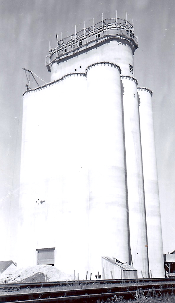
See the little cornice atop the tank? Those are forms for the cornice, the overhang. They call them eaves on a house.
The roof was poured before the headhouse went up.
That crane is a concrete-hoisting crane.
The headhouse is quite an operation because you had to hoist the concrete up to the top of the tank. And then they had a deck crane, and you had to hoist it [the concrete] to the top.
Every job I worked on, they used a nail keg that had been filled with concrete as a counterbalance weight. When you went up and down on the cable to go to work, that’s what you stood on—two guys, one foot each. That’s all there was room for.
It didn’t take that long, about fifteen or twenty seconds.
The motor and cable were down on the ground.
The operator had a shed to keep him out of the rain and sun.

It’s all done. It looks like they’re putting scaffolding up for painting. The main hoist is on the left. That’s a Georgia buggy hanging on the hoist. The guy that’s standing there is going to push it as soon as it hits the deck. They might be just starting on the headhouse. I can’t figure that scaffolding out. It’s a rigid scaffolding.

On the upper left-hand corner, there’s a crane. That crane we used to haul the steel up to the top, the rebar, the jackrods. That’s all we used it for. You didn’t tie up the other hoist, you used that one. I think it’s called a jack crane. It was an electrically operated crane. The railroad tracks are on the bottom, that’s the end of a box car in the lower right. That doorway—that’s used when you’re loading grain after the thing was all over with.
When I first started, I pushed the Georgia buggy. It’s probably the worst job in the world because it’s very physical. They weighed 1000 pounds. At Alta, I progressed to laying steel. All the new hires always got to push the concrete because that was the hardest work. There was a big turnover when you started out because pushing Georgia buggies wasn’t very much fun.
 Story and photos by Kristen Cart
The Boxholm elevator located in central Iowa was an intriguing destination, particularly since I had knowingly passed it by, missing it by a few miles on more than one trip. It became imperative to make the detour to see it. I was glad I did, since the elevator made beautiful pictures on that early summer day. I used a wide-angle lens that added pronounced distortion to the scene, causing the buildings on the edges to lean in dramatically. But the leaning lines pointed to the beautifully clouded sky.
You can use a wide-angle lens to include more of the scene from close quarters than would be possible with another lens, but you forfeit realism. This is not a problem for certain artistic photos, but it is not ideal for documentary shots. When photographing buildings where you want to preserve parallel lines, you must stand farther away and use a longer focal-length lens. At Boxholm, I did not have that option.
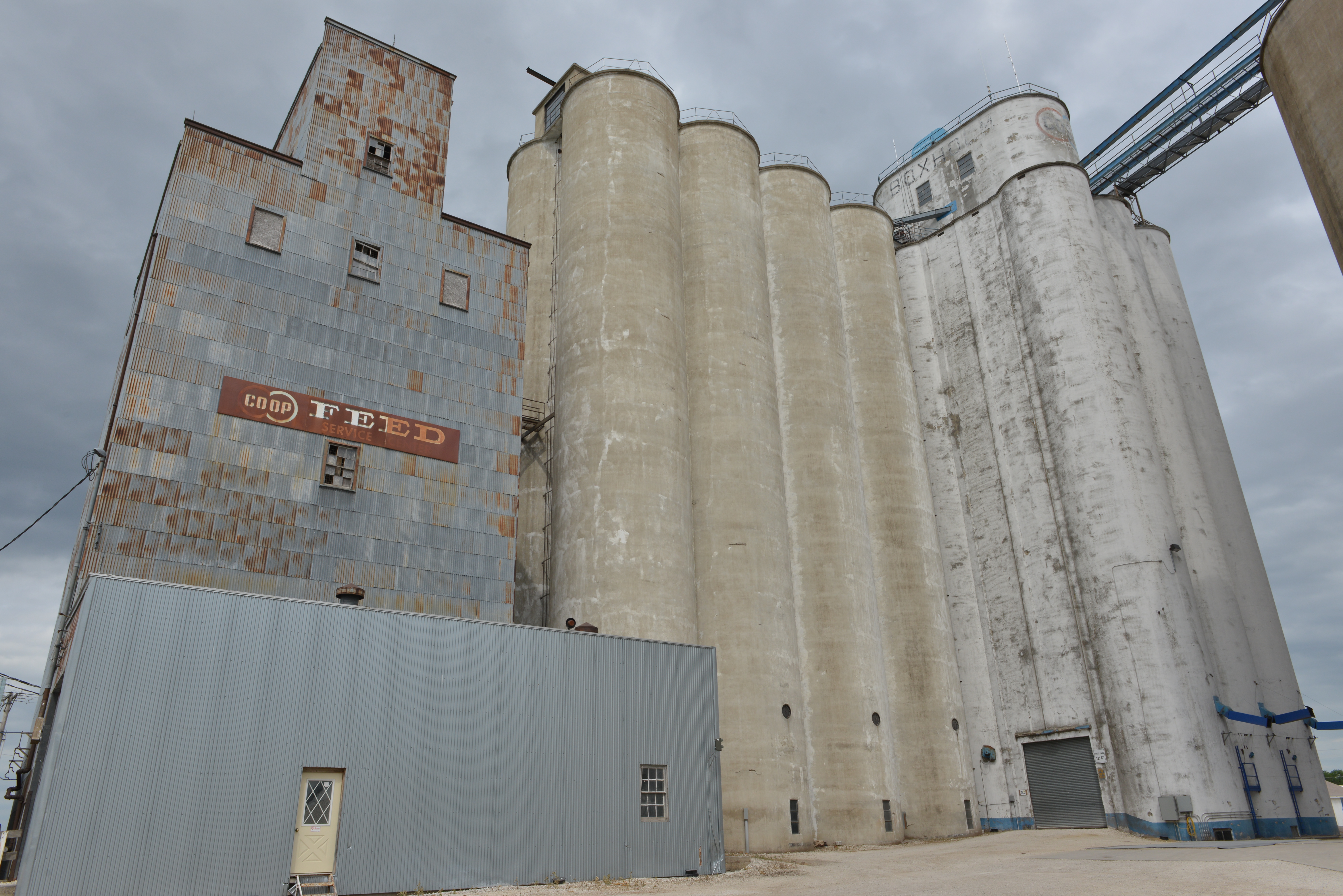
Wide-angle lens distortion is maximized in this view.
At extremely close quarters, the wide-angle lens exaggerates height and adds drama. But the distortion becomes more pronounced.
The Tillotson Construction Company of Omaha, Neb., built the elevator in 1955. An annex stands beside it, and an old wooden feed mill is beside that. A much newer elevator with the West Central logo was built later, after it became customary to leave the concrete plain, without the white finish.

A more conventional view of the elevator complex.
The specifications for the Boxholm elevator are among the Tillotson Company construction records. We learned some details about the elevator from a few stray sources before my visit; for instance, the elevator has exactly 96 light bulbs installed. Its construction followed the Drummond plan. Other projects using the same architectural plan were the elevators at Waverly, Neb., and Lahoma and Drummond, Okla.
Specifications
Capacity per plans (with Dock): 199,400 bushels
Capacity per foot of height: 2,002 bushels
Reinforced concrete per plans (total): 1,797 cubic yards
Plain concrete (3″ hoppers): 33 cubic yards
Reinforcing steel per plans (includes jack rods): 85.71 tons
Average steel per cubic yard reinforced concrete: 95.4 pounds
Steel and reinforced concrete itemized per plans:
Below main slab: 6,861 pounds steel, 59.2 cubic yards concrete
Main slab: 25,603 pounds steel, 202 cubic yards concrete
Drawform walls: 103,192 pounds steel, 1,295 cubic yards concrete
Driveway and Work floor : 3,820 pounds steel, 23.8 cubic yards concrete
Deep bin bottoms (including columns): 7,271 pounds steel, 39.3 cubic yards concrete
Overhead Bin bottoms: 6,040 pounds steel, 27.6 cubic yards concrete
Bin roof and Extension Roofs: 7,210 pounds steel, 41.7 cubic yards concrete
Scale floor (or garner complete): 160 pounds steel, 2.5 cubic yards concrete
Cupola walls (including leg & head): 7,257 pounds steel, 76 cubic yards concrete
Distributor floor: 1,560 pound steel, 9.4 cubic yards concrete
Cupola roof: 2,147 pounds steel, 15.6 cubic yards concrete
Misc. (track sink, steps, etc.): 173 pounds steel, 3.5 cubic yards concrete
Attached driveway: none
Bridge and/or Tunnel: none
Pit Liner–plain: 16 cubic yards concrete
Drier Bin Bottom: 134 pounds steel, 1.3 cubic yards concrete
Coffer Dam, Cleaner Floor: Wood
Remarks: 10 Bin Hot spot; 8 Bin Aeration tubes; Dryer bin
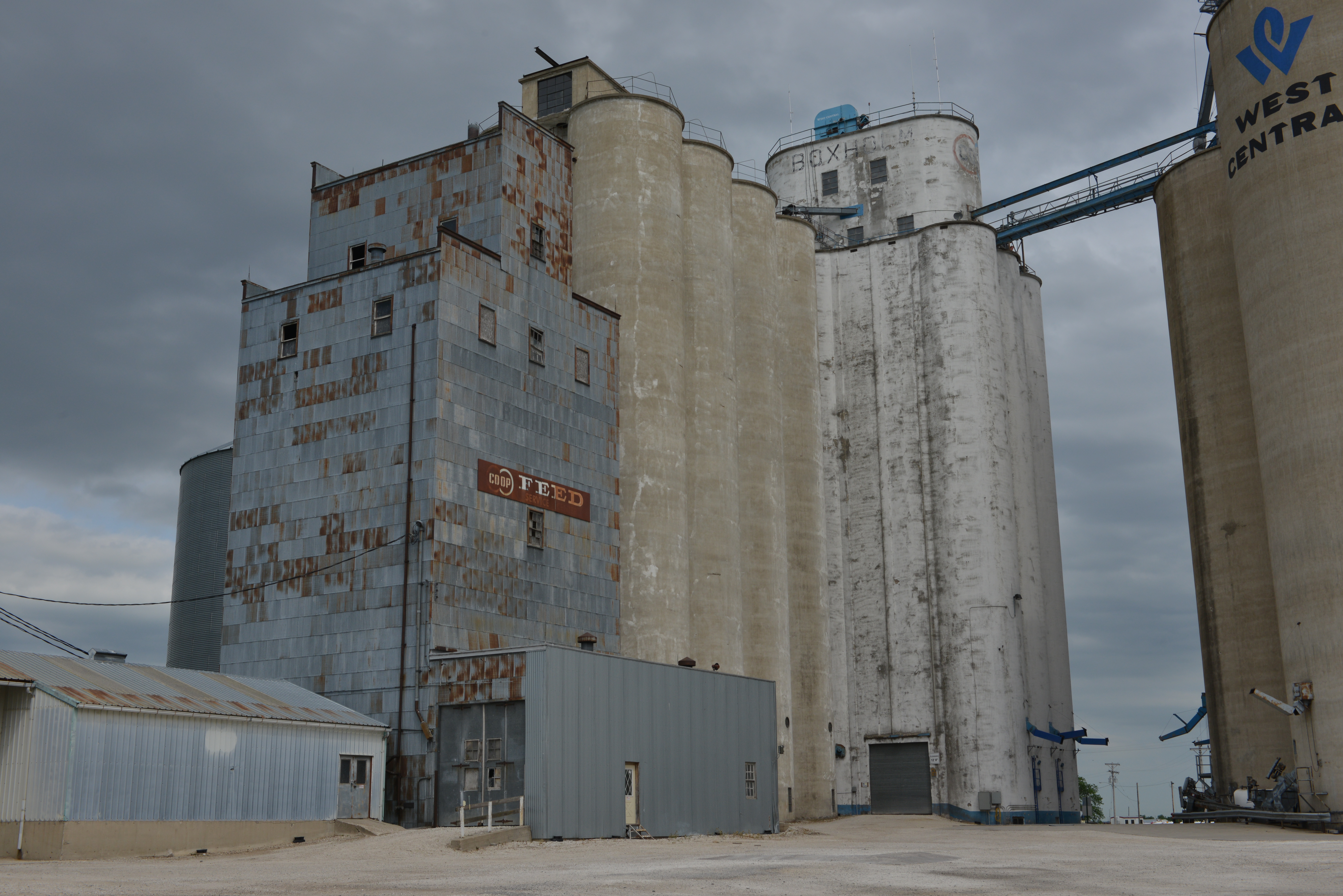
The rounded headhouse is a reliable indicator of a Tillotson elevator
Construction details
Like Waverly: construction details were identical to Waverly and not listed separately in the records.
Main slab dimensions (drive length first dimension): 56 1/2′ x 70′
Main slab area (actual outside on ground): 3,850 square feet
Weight reinforced (total) concrete (4000 pounds per cubic yard plus steel): 3,747 tons
Weight plain concrete (hoppers; 4000 pounds per cubic yard): 98 tons
Weight hopper fill sand (3000 pounds per cubic yard): 732 tons
Weight of grain (at 60 pounds per bushel): 5,982 tons
Weight of structural steel and machinery: 20 tons
Gross weight loaded: 10,579 tons
Bearing pressure: 2.75 tons per square foot
Main slab thickness: 24″ with 3″ pile cap
Main slab steel: straight #9 at 7″ spacing
Tank steel and bottom (round tanks): #4 at 12″ spacing
Lineal feet of drawform walls & extension: 606′
Height of drawform walls: 120′
Pit depth below main slab: 15’3″
Cupola dimensions (outside width x length x height): 22 1/4′ x 48 1/2′ x 35′
Pulley centers: 160.75′
Number of legs: 1
Distributor floor: yes
Track sink: yes
Full basement: yes
Electrical room: yes
Driveway width clear: 13′
Dump grate size: 2 at 9′ x 5′ and 9′ x 15′
Column under tanks size: 16″ square
Boot legs and head: concrete
 Machinery details
Boot pulley: 72″ x 14″ x 4 15/16″
Head pulley: 72″ x 14″ x 2 7/16″
R.P.M. Head pulley: 42
Belt: 335′, 14″ 6 ply Calumet
Cups: 12″ x 6″ at 8″ spacing
Head drive: Howell 40 horsepower [4 circled here]
Theoretical leg capacity (cup manufacturers rating): 8,440 bushels per hour
Actual leg capacity (80% of theoretical rating): 6,750 bushels per hour
Horsepower required for leg (based on actual capacity): 32 horsepower
Man lift: 1 1/2 horsepower Ehr.
Load out scale: 25 Bushel
Load out spout: 10″ diameter
Truck lift: 7 1/2 horsepower Ehr.
Dust collector system: Fan to bin
Cupola spouting: 10″ diameter
Driveway doors: 2 overhead rolling
Conveyor: provision
Remarks
see page 10 (above)

It was commercial power for the lamps. The only thing that was noisy was the mixer and the hoist. Once you got about 40 feet off the ground, all that anybody heard was people talking to each other. That’s the top of the driveway (seen in the photo), about 16 feet, so they’re about 25 or 30 feet off the ground. On a construction site, there’s lumber all over everywhere. Today they keep track of it very carefully because people steal it. But when we were building these, nobody stole lumber. People in Iowa and the Midwest, they didn’t steal lumber from a construction site like they do out here (California.) See the scaffolding below the forms? A cement finisher finished the concrete as it came out of the forms. That’s all he did, all night long.

Those cars…I didn’t have a car at Alta. Those shacks were probably, lower right, the office, and the other was where we kept the tools. We built a lot of those things and then we tore them down. Slip-form construction was a major engineering feat. They built concrete grain elevators before slip-forms. They had steel forms they’d fill with concrete.

They often say, a picture is worth a thousand words and this one fits the bill perfectly. The photo is truly an aid to describing the method of slipform construction that was used in grain elevator construction. Neil mentions the one-handed placement of the jack rod, so I’ll start with that.
Slipform construction is made up of many complex disciplines which have to all work together in order to provide the final poured-in-place concrete product.
As mentioned prior to this, the slipping of the formwork used in this type of construction was provided by a series of screw jacks placed apart by an engineered calculation sufficient to lift each jack’s portion of the formwork assembly.
Each screw jack was supported by a wooden, U-shaped yoke, the legs of which were attached to the vertical concrete formwork. Inserted in the top (or horizontal) portion of each yoke was a screw jack (similar to that used in jacking building foundations). A smooth one-inch jack rod was then inserted into the top head of the jack and threaded down through it until stopping at the foundation slab.
The wooden formwork is clearly seen at the Alta elevator rises. The scaffolding around the bottom was for the cement finishers, who smoothed and patched the freshly formed surface. Photo from the Neil A. Lieb Archive.
A series of horizontal wooden rails at about waist height (looks like a railroad track) were then built directly above the open formwork, the “ties” of which were placed at prescribed intervals and used as a template spacer for inserting the actual vertical reinforcing steel. (See the small, half-inch rebar rods extending vertically out of the open bin forms at each cross tie). The vertical rebar was staggered slightly in an alternating fashion so as to allow the half-inch horizontal rebar to be threaded through the vertical rebar. On the vertical 2x4s that are attached to the exterior side of the formwork and rise above the entire deck assembly, so-called targets placed on their tops were used in leveling the deck in order to provide a final elevator that rose plumb and straight above the foundation.
As the screw jacks were turned (each jack was turned the same amount), the foreman on deck used a leveling instrument and sighted on each target to insure that the formwork was rising true plumb and level. If any of the targets did not align with true level, the portion of the deck out of plumb was corrected by extra turns of the screw jack or jacks as necessary to bring that portion of the deck up level with the rest of the formwork.
Not shown in the photo is the horizontal rebar that was required to form a steel reinforced grid integrally cast in the concrete to form a reinforced concrete structure. Initially, the horizontal steel was wire-tied in place to the vertical rebar prior to one side of the forms being installed. This placement occurred only to the height of the wood bin forms. Once the form-lifting began, the horizontal steel was placed by hand by pushing and threading the rebar horizontally through the vertical rebar. Because of the vertical movement of the formwork, close attention was required as to the spacing between horizontal rebar.
Now, try to imagine: the start gun is fired and the continuous action of the many processes begins, never to stop until the wooden forms and finished structure reaches the prescribed vertical height (some 120 feet) eight days later. Manual labor is involved in each discipline. Personnel changes occur, but each position is filled by a replacement. The gun is fired, cement is mixed and lifted to the deck of the formwork via a Georgia buggy, and the content is dumped into the open form. The pouring of the cement into the formwork is continued in a circular fashion around the entire deck until it reaches a prescribed height in the form.

The finished elevator. Photo from the Neil A. Lieb Archive.
Once the cement is allowed to solidify in the forms on the foundation slab, the jacking operation begins and the formwork starts its vertical lifting and slipping process. The jacks are turned, the cement is poured, the vertical rebar and jackrods are placed and spliced, and all the while the horizontal rebar is positioned at the proper height and spacing. Pour cement, turn jacks, place rebar, check deck level, and on and on through night and day until the construction reaches final height. The most problematic aspect of this system is the placing of the horizontal steel at the correct spacing, the placement of formed openings in the bins, keeping the hoist in operation, mixing the cement, and obtaining enough set time of the cement mixture so that as the finished concrete walls do not fall apart or slough off.
Also, hanging beneath the formwork structure is the scaffolding for the cement finishers who dutifully serve to patch and smoothly finish the concrete surfaces appearing at the bottom of the vertically slipping formwork.
